4 layers108 × 69 mm
Fmc2sata
antmicro/fmc-sata-adapter
Adapter board exposing SATA M.2 SSD on FMC board-to-board connector
65 parts17Apache-2.0
Texas InstrumentsExtended
-40℃~+125℃@(TJ) 1 4.5V~17V 500kHz 5A 760mV~7V Adjustable Buck Buck Built-in Yes TSOT-23-6 DC-DC Converters ROHS
The TPS565208DDC is a DC DC Converter made by Texas Instruments in a TSOT-23-6 package with 6 pins. -40℃~+125℃@(TJ) 1 4.5V~17V 500kHz 5A 760mV~7V Adjustable Buck Buck Built-in Yes TSOT-23-6 DC-DC Converters ROHS.
PCBKit's library has its KiCad symbol (Regulator_Switching:TPS565208, from KiCad's library) and its footprint (Package_TO_SOT_SMD:SOT-23-6, from KiCad's library), ready for a KiCad board. 4,860 are in stock at JLCPCB (part C2650336). 31 open-source boards in 26 repositories on GitHub use it.
| Parameter | Conditions | As printed | Page |
|---|---|---|---|
| Input voltage | VIN, EN | min -0.3 · max 19 V | 4 |
| Input voltage | VBST | min -0.3 · max 25 V | 4 |
| Input voltage | VBST (10 ns transient) | min -0.3 · max 27 V | 4 |
| Input voltage | VBST (vs SW) | min -0.3 · max 6.5 V | 4 |
| Input voltage | VFB | min -0.3 · max 6.5 V | 4 |
| Input voltage | SW | min -2 · max 19 V | 4 |
| Input voltage | SW (10 ns transient) | min -3.5 · max 21 V | 4 |
| Operating junction temperature TJ | min -40 · max 150 °C | 4 | |
| Storage temperature Tstg | min -55 · max 150 °C | 4 | |
| Electrostatic discharge V(ESD) | Human-body model (HBM), per ANSI/ESDA/JEDEC JS-001 | min -4000 · max 4000 V | 4 |
| Electrostatic discharge V(ESD) | Charged-device model (CDM), per JEDEC specification JESD22-C101 | min -1500 · max 1500 V | 4 |
| Supply input voltage range VIN | min 4.5 · max 17 V | 4 | |
| Input voltage range VI | VBST | min -0.1 · max 23 V | 4 |
| Input voltage range VI | VBST (10 ns transient) | min -0.1 · max 26 V | 4 |
| Input voltage range VI | VBST (vs SW) | min -0.1 · max 6 V | 4 |
| Input voltage range VI | EN | min -0.1 · max 17 V | 4 |
| Input voltage range VI | VFB | min -0.1 · max 5.5 V | 4 |
| Input voltage range VI | SW | min -1.8 · max 17 V | 4 |
| Input voltage range VI | SW (10 ns transient) | min -3.5 · max 20 V | 4 |
| Operating junction temperature TJ | min -40 · max 125 °C | 4 | |
| Junction-to-ambient thermal resistance RθJA | DDC (SOT), 6 PINS | typ 95.9 °C/W | 4 |
| Junction-to-case (top) thermal resistance RθJC(top) | DDC (SOT), 6 PINS | typ 35.6 °C/W | 4 |
| Junction-to-board thermal resistance RθJB | DDC (SOT), 6 PINS | typ 16.4 °C/W | 4 |
| Junction-to-top characterization parameter ψJT | DDC (SOT), 6 PINS | typ 1.4 °C/W | 4 |
| Junction-to-board characterization parameter ψJB | DDC (SOT), 6 PINS | typ 16.4 °C/W | 4 |
| Operating – non-switching supply current IVIN | TJ = –40°C to 125°C, VIN = 12 V; VIN current, EN = 5 V, VFB = 1 V | typ 590 · max 780 uA | 5 |
| Shutdown supply current IVINSDN | TJ = –40°C to 125°C, VIN = 12 V; VIN current, EN = 0 V | typ 0.8 · max 5 uA | 5 |
| EN high-level input voltage VENH | TJ = –40°C to 125°C, VIN = 12 V | min 1.6 V | 5 |
| EN low-level input voltage VENL | TJ = –40°C to 125°C, VIN = 12 V | max 0.8 V | 5 |
| EN pin resistance to GND REN | TJ = –40°C to 125°C, VIN = 12 V; VEN = 12 V | min 120 · typ 245 · max 400 kΩ | 5 |
| VFB threshold voltage VFBTH | TJ = –40°C to 125°C, VIN = 12 V | min 753 · typ 760 · max 767 mV | 5 |
| VFB input current IVFB | VIN = 12 V; TA = 25°C, VFB = 0.8 V | typ 0 · max 0.1 uA | 5 |
| High-side switch resistance RDS(on)h | VIN = 12 V; TA = 25°C, VBST – VSW= 5.5 V | typ 31 mΩ | 5 |
| Low-side switch resistance RDS(on)l | VIN = 12 V; TA = 25°C | typ 16 mΩ | 5 |
| Current limit IOCL | TJ = –40°C to 125°C, VIN = 12 V | min 5.3 · typ 6.7 · max 8 A | 5 |
| Thermal shutdown threshold TSDN | Shutdown temperature; VIN = 12 V; not production tested | typ 172 °C | 5 |
| Thermal shutdown threshold TSDN | Hysteresis; VIN = 12 V; not production tested | typ 38 °C | 5 |
| Minimum off time tOFF(MIN) | TJ = –40°C to 125°C, VIN = 12 V; VFB = 0.61 V | typ 236 · max 280 ns | 5 |
| Soft-start time tSS | TJ = –40°C to 125°C, VIN = 12 V; Internal soft-start time | typ 1 ms | 5 |
| Switching frequency FSW | TJ = –40°C to 125°C; VIN = 12 V, VOUT = 5 V, CCM mode | typ 500 kHz | 5 |
| Output UVP threshold VUVP | TJ = –40°C to 125°C, VIN = 12 V; Hiccup detect (H > L) | typ 65 % | 5 |
| Hiccup on time THICCUP_WAIT | TJ = –40°C to 125°C, VIN = 12 V | typ 1.8 ms | 5 |
| Hiccup time before restart THICCUP_RE | TJ = –40°C to 125°C, VIN = 12 V | typ 14.9 ms | 5 |
| UVLO threshold UVLO | TJ = –40°C to 125°C; Wake up VIN voltage | typ 4 · max 4.3 V | 5 |
| UVLO threshold UVLO | TJ = –40°C to 125°C; Shutdown VIN voltage | min 3.3 · typ 3.6 V | 5 |
| UVLO threshold UVLO | TJ = –40°C to 125°C; Hysteresis VIN voltage; not production tested | typ 0.4 V | 5 |
antmicro/fmc-sata-adapter
Adapter board exposing SATA M.2 SSD on FMC board-to-board connector

RICCIARDI-Adrien/Cyclope
Raspberry Pi powered robot with camera live stream and 360° lidar.

Fiberprinter/fiberprinter-electronics
Fiberelectronics Control every pulse, master every micron

InSynchronous/mango
An ESP32-S3 based flight computer with an external flash, imu, barometer, magnetometer, 4 servo ports, and 4 pyrotechnic channels with MOSFETs. Designed for Aerospace applications.
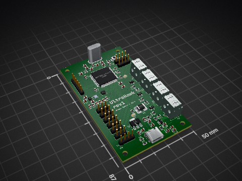
InSynchronous/UltraHawk
A custom flight computer designed for drones and flight computers.

ben-labs-ltd/BL-N305X
Meshtastic intended LoRa Node - Ben Labs Node 30.5dBm

Gold-Rush-Robotics/pcb_2024
A repository to store work done on PCBs for the 2024 season

akashh218/Variable-DC-DC-Buck-Converter
A custom 5A variable buck converter designed in KiCad, supporting a 4–17V input range and an adjustable 1–7V output, with a focus on compact power-stage layout, efficient power delivery, thermal management, and…

Yes. The symbol is Regulator_Switching:TPS565208 and the footprint Package_TO_SOT_SMD:SOT-23-6, both drawn on this page. PCBKit places them on a board for you when you design with it.
TSOT-23-6, with 6 pins. Its footprint is drawn on this page.
Texas Instruments publishes it: the Datasheet link on this page opens it.
JLCPCB lists it as part C2650336, with 4,860 in stock; the sellers' links on this page open their listings.
Parts like it in the library: the TPS565201DDC by Texas Instruments, the RT6255BHGJ6F by Richtek Tech, the TMI3255SF by TMI and the RT6255AHGJ6F by Richtek Tech. Check their datasheets: a part that fits the footprint may still differ in its ratings.
31 boards in 26 repositories on GitHub; the most starred are listed on this page, with their KiCad files.