Skip to the content
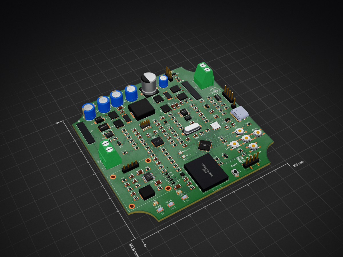
4 layers100 × 99.9 mmSolar Project Rev1, the printed circuit board in 3D

Solar Project Rev1

Phil-CIA/Solar-Project-200w

Solar Project 200W is a prototype-first hardware and firmware effort for a 200W-class solar charging system built around a 4S LiFePO4 battery domain.

Size
100 × 99.9 mm
Copper layers
4
Thickness
1.79 mm
Parts
174
Nets
181
Pads
709
Tracks, vias
1,536, 274
Pours
10
Routed
Yes
KiCad
KiCad 10.0 (file 20260206)
Created
6 Jul 2026
Updated
6 Nov 2026

Overview

Solar Project Rev1 is an open-source printed circuit board by Phil-CIA, from the Phil-CIA/Solar-Project-200w repository on GitHub. It is a 4-layer board of 100 × 99.9 mm with 174 parts on 181 nets, routed with 1,536 tracks and 274 vias.

It is built around the STM32G431CBU6, CP2102-GMR and ESP32-C3-MINI-1, with the AHT20, INA213AIDCKR(LX) and LM5163DDA among its other parts. Its parts include 74 resistors, 42 capacitors, 11 ICs, 10 diodes and 6 transistors. It belongs with the power boards and the ESP32, STM32 and RISC-V boards of this library.

Main components

12

README

README.md

Solar Project 200W

Solar Project 200W is a prototype-first hardware and firmware effort for a 200W-class solar charging system built around a 4S LiFePO4 battery domain.

What this repository is for

  • Designing and validating a safe MPPT charger path
  • Defining control, telemetry, and protection behavior
  • Tracking design decisions, handoffs, and bring-up evidence

Current Rev 1 focus

  • Only Rev 0 and Rev 1 exist; Rev 1 is the current production revision. The production release at C:\Users\user\OneDrive\JLCPCB files\Solar Charger\Rev 1 is authoritative for board identity, manufacturing and board-specific tests. Repository copies support continued development; the schematic, project and BOM differences are described in the board notes.
  • Rev 1 is assembled; the supplied manufacturing package and both-side photos are recorded in board notes.
  • Continue with practical low-energy bring-up and Rev 1 firmware, using the development tracker and working plan.
  • This is a hobby prototype: keep useful notes and relevant checks, not a formal lab dossier. Assembly does not establish working charging or full-power performance.
  • Rev 1 STM32G473 bring-up firmware through ff89791 is already on main; see firmware notes. That is development progress, not proof of board compatibility or a passing powered test.

System baseline

  • PV class: 2x100W panels in parallel (DEC-051)
  • Battery class: 12.8V LiFePO4 (4S)
  • Rev 1 design targets: 125 W continuous output, 150 W maximum PV operating power, 8-10 A nominal charging, approximately 12 A hardware protection pending verification

Project structure

  • docs/: requirements, architecture, decisions, test plans, phase reviews
  • hardware/: KiCad files, MPPT notes, wiring maps, implementation checklists
  • firmware/: firmware workspace and bring-up software notes

Start here

  1. HANDOFF.md - current checkpoint and next step
  2. docs/rev-one-board-notes.md - working board baseline and known differences
  3. docs/README.md - engineering references
  4. docs/decisions-log.md - retained design decisions
  5. SOLAR_HANDOFF_2026-09-19.md and SOLAR_HANDOFF_2026-09-18.md for the historical Rev 1 fabrication closeout
  6. hardware/kicad/solar-project/REVISION-INDEX.md for KiCad source-of-truth rules

Simulation workflow

The PV switch gate-drive concept should be verified with SPICE as part of the normal review loop. The project-local LTspice assets are in hardware/kicad/solar-project/spice, including the schematic draft hardware/kicad/solar-project/spice/pv_switch_gate_drive.asc and the launcher hardware/kicad/solar-project/spice/run_ltspice_pv_gate_drive.cmd.

A provisional LTspice integration harness is also present at hardware/kicad/solar-project/spice/90_system_integration_harness_ltspice.cir. It is a simplified, staged model of the PV input, buck power stage, and battery boundary. The current run converged to about 13.64 V at the output node and 13.98 V at the battery bus at 4 ms, which is consistent with a basic charging path but still not hardware-validated.

Earlier simulation identified a gate-drive margin problem in the arrangement it modeled. That historical result is not a measured failure of the assembled Rev 1 U14/Q5/Q6 protection circuit; confirm the topology against the Rev 1 production release and use matching low-energy checks before drawing that conclusion.

Safety notice

This project includes high-current DC power electronics and planned AC-domain integration. Use staged, current-limited bring-up and treat all safety checks as mandatory gates.

Session continuity

Parts

174
QtyValueFootprintReferences
15100nFPCM_JLCPCB:C_0805C1, C8, C12, C22, C23, C28, C33, C44, C45, C46, C47, C48, C51, C54, C57
1410kΩPCM_JLCPCB:R_0805R6, R19, R34, R36, R47, R48, R50, R53, R54, R55, R56, R57, R58, R59
1010ΩPCM_JLCPCB:R_0805R4, R26, R27, R41, R65, R69, R70, R71, R72, R73
8100kΩPCM_JLCPCB:R_0805R1, R2, R32, R38, R40, R43, R67, R74
5Tactile Button, 160gfPCM_JLCPCB:SW-SMD_4P-L5.1-W5.1-P3.70-LS6.5-TL-2SW1, SW2, SW3, SW4, SW5
40ΩPCM_JLCPCB:R_0805R33, R49, R63, R64
41N5819WSPCM_JLCPCB:D_SOD-323D4, D6, D7, D10
42.2uFPCM_JLCPCB:C_1206C7, C15, C34, C35
447uFCapacitor_THT:CP_Radial_D8.0mm_P3.50mmC19, C21, C30, C31
45015TestPoint:TestPoint_Keystone_5015_Micro_MiniTP15, TP16, TP17, TP18
4CSD18540Q5BPackage_TO_SOT_SMD:TDSON-8-1M1, M2, M3, M4
31uFPCM_JLCPCB:C_0805C2, C55, C56
320kΩPCM_JLCPCB:R_0805R7, R10, R61
32N7002KPCM_JLCPCB:Q_SOT-23Q2, Q3, Q7
34.7kΩPCM_JLCPCB:R_0805R5, R44, R45
20.001ohmsResistor_SMD:R_Shunt_Vishay_WSK2512_6332Metric_T2.66mmR16, R22
2100uFPCM_JLCPCB:C_1206C14, C53
21SMA4742APCM_JLCPCB:D_DO-214AC(SMA)D1, D5
21kΩPCM_JLCPCB:R_0805R42, R52
22.2MΩPCM_JLCPCB:R_0805R37, R66
22.2nFPCM_JLCPCB:C_0805C9, C13
222uFPCM_JLCPCB:C_0805C27, C29
2330ΩPCM_JLCPCB:R_0805R11, R39
233pFPCM_JLCPCB:C_0805C49, C50
23522-21My_Parts_ Passive:Automotive fuse holder keystone 3522-2_KEYF1, F2
25.1kΩPCM_JLCPCB:R_0805R24, R62
25.62kPCM_JLCPCB:R_0805R17, R25
276.8kPCM_JLCPCB:R_0805R3, R18
2BSC040N10NS5Package_TO_SOT_SMD:TDSON-8-1Q5, Q6
2Screw_Terminal_01x02TerminalBlock_Phoenix:TerminalBlock_Phoenix_MKDS-1,5-2-5.08_1x02_P5.08mm_HorizontalJ1, J3
2WS2812BPCM_JLCPCB:LED-SMD_4P-L1.6-W1.5_XL-1615RGBC-WS2812BD8, D11
2~1My_Parts_ Passive:10mm LOGO10mm1, 10mm2
11.3kPCM_JLCPCB:R_0805R68
11.5kΩPCM_JLCPCB:R_0805R60
11.5nFPCM_JLCPCB:C_0805C25
1100uFCapacitor_THT:CP_Radial_D6.3mm_P2.50mmC3
1102kPCM_JLCPCB:R_0805R21
1180kPCM_JLCPCB:R_0805R9
1180kΩPCM_JLCPCB:R_0805R35
1180pFPCM_JLCPCB:C_0805C20
11MΩPCM_JLCPCB:R_0805R13
12.43kPCM_JLCPCB:R_0805R31
12.7kΩPCM_JLCPCB:R_0805R51
120.5kPCM_JLCPCB:R_0805R29
120021121-00010C4LFdigikey-footprints:PinHeader_2x5_P1.27mmJ6
1220nFPCM_JLCPCB:C_0805C52
122nFPCM_JLCPCB:C_0805C24
127kΩPCM_JLCPCB:R_0805R8
12kΩPCM_JLCPCB:R_0805R15
1330kΩPCM_JLCPCB:R_0805R14
133nFPCM_JLCPCB:C_0805C26
140.2kPCM_JLCPCB:R_0805R30
147pFPCM_JLCPCB:C_0805C10
1499kPCM_JLCPCB:R_0805R20
151.7kPCM_JLCPCB:R_0805R28
1560uFCapacitor_SMD:CP_Elec_10x12.6C18
16.8kΩPCM_JLCPCB:R_0805R12
175kΩPCM_JLCPCB:R_0805R23
182kΩPCM_JLCPCB:R_0805R46
1AHT201My_Parts_ ICs:Humidity sensorU7
1CP2102-GMRPCM_JLCPCB:WQFN-28_L5.0-W5.0-P0.50-BL-EP3.2U3
1Conn_01x04Connector_PinHeader_2.54mm:PinHeader_1x04_P2.54mm_VerticalJ8
1Conn_01x04Connector_PinHeader_2.54mm:PinHeader_1x04_P2.54mm_Vertical_SMD_Pin1RightJ4
1ESP32_C3_mini1My_Parts_ MPUs:ESP32 C3 miniU2
1FanConnector_PinHeader_2.54mm:PinHeader_1x03_P2.54mm_VerticalJ7
1GreenPCM_JLCPCB:D_0805D9
1HSBA0119Package_DFN_QFN:PQFN-8-EP_6x5mm_P1.27mm_GenericQ4
1INA213AIDCKRPCM_JLCPCB:SOT-363_SC-70-6U10
1LInductor_SMD:L_KOHERelec_MDA7030L3
1LInductor_SMD:L_APV_APH1240L2
1LM5163Package_SO:Texas_R-PDSO-G8_EP2.95x4.9mm_Mask2.4x3.1mm_ThermalViasU4
1LM51772QRHARQ1digikey-footprints:VFQFN-40-1EP_6x6mmU6
1LM74502HDDFRPackage_TO_SOT_SMD:Texas_DDF0008A_SOT-8_1.6x2.9mm_P0.65mmU14
1LMV393Package_SO:SOIC-8-1EP_3.9x4.9mm_P1.27mm_EP2.29x3mm_ThermalViasU9
1LP5912-3.3DRVPackage_SON:WSON-6-1EP_2x2mm_P0.65mm_EP1x1.6mm_ThermalViasU5
1SMBJ48CAPCM_JLCPCB:D_SMBD2
1SSD1306_OLED1My_Parts_ ICs:0.96 inOLED display SSD1306U8
1STM32G431CBU6Package_DFN_QFN:QFN-48-1EP_7x7mm_P0.5mm_EP5.6x5.6mmU1
1Tactile Button, 160gfPCM_JLCPCB:SW_TS-1088-AR02016S1
1TestPoint_SmallConnector_PinHeader_2.54mm:PinHeader_1x01_P2.54mm_VerticalTP1

The 170 most common of 174 parts.

More from Phil-CIA/Solar-Project-200w

1
  • 4 layers100 × 99.9 mmSolar Project Rev0 - Manufactured First Build, the printed circuit board in 3D

    Solar Project Rev0 - Manufactured First Build

    Phil-CIA/Solar-Project-200w

    Solar Project 200W is a prototype-first hardware and firmware effort for a 200W-class solar charging system built around a 4S LiFePO4 battery domain.

    163 parts

Similar boards

  • 2 layers100 × 125 mmDSP Regulator RevC, the printed circuit board in 3D

    DSP Regulator RevC

    Phil-CIA/Development-Station-Power-Supply

    3 channel bench supply with current and voltage plotting

    235 parts
  • 2 layers100 × 100 mmOutdoor carrier, the printed circuit board in 3D

    Outdoor carrier

    mrknockknockgaming-droid/hvac-monitor

    Fullscope monitors a home's heat pump or air conditioner continuously, the way a technician would with gauges on it, and tells the contractor and the homeowner when something is going wrong, before it becomes a no-cool…

    70 parts
  • 2 layers195.3 × 64.3 mmSpotwelderix, the printed circuit board in 3D

    Spotwelderix

    swifty99/Spotwelderix

    Spotwelderix

    90 parts2GPL-3.0
  • 2 layers310 × 100 mmAOML AB 3.0 reorganized v2, the printed circuit board in 3D

    AOML AB 3.0 reorganized v2

    cxs1529/XBT_Autolauncher_PCB

    KiCAD repository for the XBT Autolauncher board

    247 parts
  • 2 layers65 × 56 mmInterface board, the printed circuit board in 3D

    Interface board

    TrendBit/SMBR-hardware

    Design file for SMBR hardware modules in KiCAD.

    133 partsGPL-3.0
  • 4 layers90 × 50 mmGreenmobi bms, the printed circuit board in 3D

    Greenmobi bms

    G-Pereira/greenmobi-bms

    A VESC compatible battery management system

    141 parts31CERN-OHL-S-2.0
  • 4 layers100.3 × 50.3 mmGreenmobi drive, the printed circuit board in 3D

    Greenmobi drive

    G-Pereira/greenmobi-drive

    A FOC motor drive compatible with VESC

    160 parts1CERN-OHL-S-2.0

Questions

How big is the Solar Project Rev1 PCB?

It measures 100 × 99.9 mm and has 4 copper layers, 1.79 mm thick.

What parts does the Solar Project Rev1 use?

174 parts, built around the STM32G431CBU6, CP2102-GMR, ESP32-C3-MINI-1 and AHT20. The full list of its parts is on this page, with links to each part's symbol and footprint where PCBKit's library has them.

Where can I download the Solar Project Rev1 KiCad files?

From the Phil-CIA/Solar-Project-200w repository on GitHub, at the commit this page was made from: the board is hardware/kicad/solar-project/Solar Project Rev1.kicad_pcb and its schematic Solar Project Rev0 - Manufactured First Build.kicad_sch. PCBKit opens the board in the browser, with nothing to install.

Can I use the Solar Project Rev1 design in my own project?

Its repository states no licence, so its author keeps all rights: ask Phil-CIA before reusing the design.