2 layers220.1 × 98 mm

 AmericanRework/Pico-2x-BLDC7
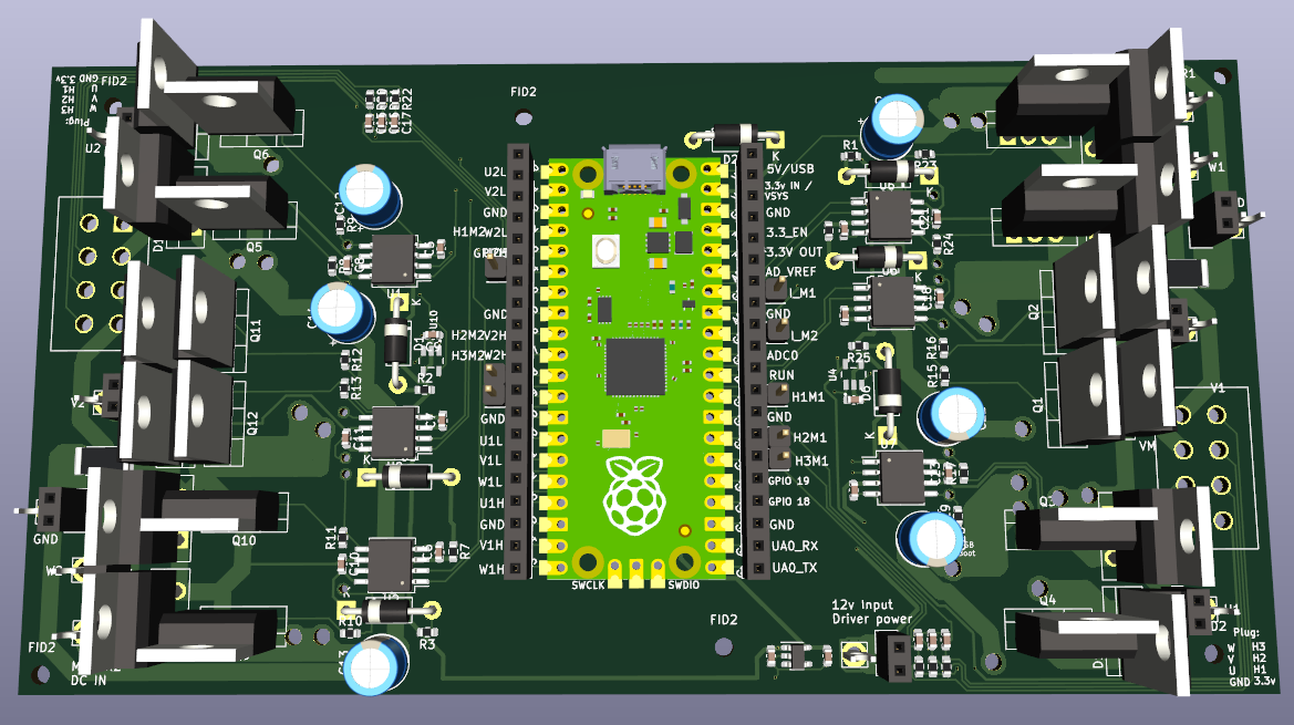
One RP2040 Pico drives two brushless motors! SimpleFOC + Halls + 2304 drivers + TO-220 mosfets or IGBTs. Plugs directly into 450x automower motors. Trying for low cost + lots of flexibility + solder it at home + repairable. Works as a 3x DC motor controller as well.
2xBLDCPicoV3 is an open-source printed circuit board by AmericanRework, from the AmericanRework/Pico-2x-BLDC repository on GitHub. It is a 4-layer board of 147.8 × 77 mm with 135 parts on 97 nets, routed with 1,946 tracks and 74 vias.
It is built around the STGP10NC60H, IRS2304PBF and XC6220B331MR, with the C3D10060A, IRF540N and UF4007 among its other parts. Its parts include 28 capacitors, 26 resistors, 23 connectors, 19 diodes and 12 transistors. It belongs with the robots and motor control boards and the RP2040 boards of this library.


One RP2040 Pico drives two brushless motors! Uses SimpleFOC + Halls + TO-220 mosfets or IGBTs. Trying for low cost + lots of flexibility + solder it yourself at home + repairable. Works as a 3x DC motor controller as well.
Features:
RP2040 Pico running Simplefoc (https://simplefoc.com/) and using halls (or -untested but should be possible- encoders) for motor commutation. (No FOC - RP2040 doesn't have enough A/D channels for 2x motor FOC.) Current sensing: 1 A/D channel and shunt resistor per motor. Uses 2304 half-H drivers. Can assemble only half the board if you only want one servo amp / want more pico I/O's. Spot for big diodes if you want 'em - Big motors seem to eat my mosfet body diodes rather quickly and IGBT's don't have body diodes.
Control via usb serial or hardware serial. I2C, SPI, and software CAN might work but are untested. Serial is Human readable, following the simplefoc commander schema: AE1 enables motor, A10 sets motor A to 10 rev/sec, A0 stops motor A. AE0 quickly drops power to motor a. etc... B10 sets motor B to 10 rev/sec... etc... This allows you to control, test, and modify this servo amp right from the Arduino IDE or pretty much anything with a USB port or serial port.
Boards have a spot for molex plugs that are pin compatible with Husqvarna 450x automower drive motors. (NOT the cut motor - it's a different pinout but you can re-pin the cut motor - see additionalNotes.txt)
Board requires your motor power DC source, and ~12vdc@ say 50mA. The board can either make 3.3v for the RP2040 pico, or you can provide external 3.3v.
There's a very simple heartbeat signal in the code - if the amp doesn't get an instruction from serial it'll shut down, or delete that line to go forever!
Assembly/Setup:
Boards require SMD paste soldering and normal soldering to build:
Assembled board:
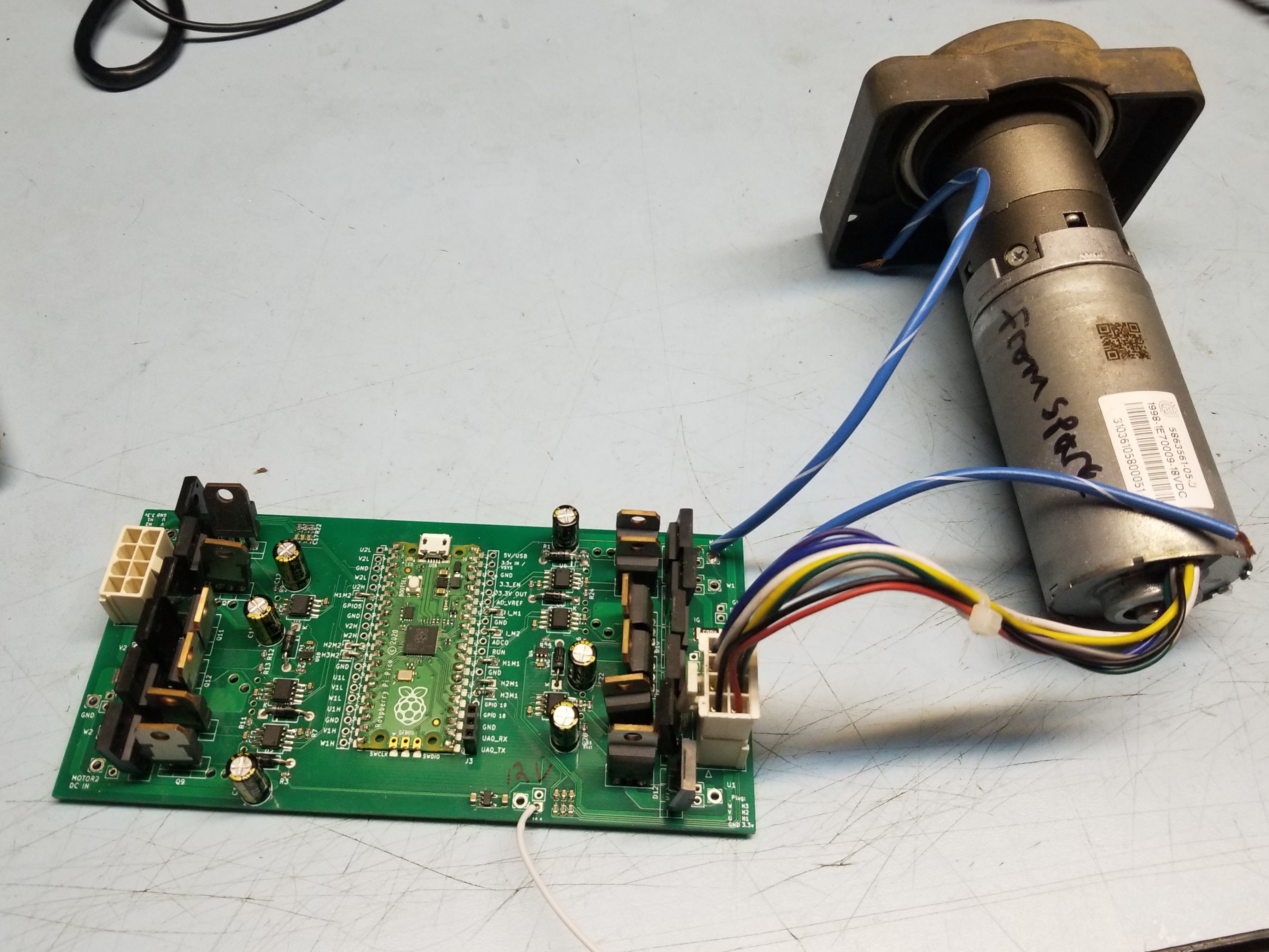
If you don't want to use the A/D (or want to repurpose any other inputs/outputs after you get a board) you can cut the trace to that pin(ehhh. update. not all the traces can be cut. is on hit list for next version), and there's a tinned hole for you to take over. And again, you don't have to build both servo amps if you want more IO's.
'Firmware' for the rp2040 has some basic configuration and setup instructions in comments at the top of the code. It's pretty well tested and has been running on 2 boards for months without failing on an automower. Open up Arduino ide, install libraries: SimpleFOC, SimpleFOC drivers, and the Earle Philhower rp2040 core, compile and upload to your pico, good to go. Check top of the firmware file (RP2040SFocAmp.ino) for various additional documentation that might help you get started.
There are two other firmware versions - one example for 3x DC motors, and one old version based on (https://github.com/ClemensElflein/xESC2040/tree/main/firmware/src) that does not use simplefoc. Both 'other' firmware versions need their pins.h file checked to be sure they follow the current board pico pin assignments, but should be somewhat functional other than that afaik. Let's call them good starting points.
Tested
Tested using velocity control and torque control up to 10A/21v. You'll want heatsinks and low rdson mosfets to get to 10A. Tested the half-h drivers with igbts and better mosfets on a big inductive load to 60V, will update as we test more. Two boards are running in a Husqvarna 450x Automower as I write this. Maybe 10 hours of operation so far. Will update if/when anything fails. Update: ~100hrs of mowing, 0 servo amp faults/problems. Will still update if/when anything fails.
2 amps, 3 motors. One board has both drive motors, one has the cut motor.
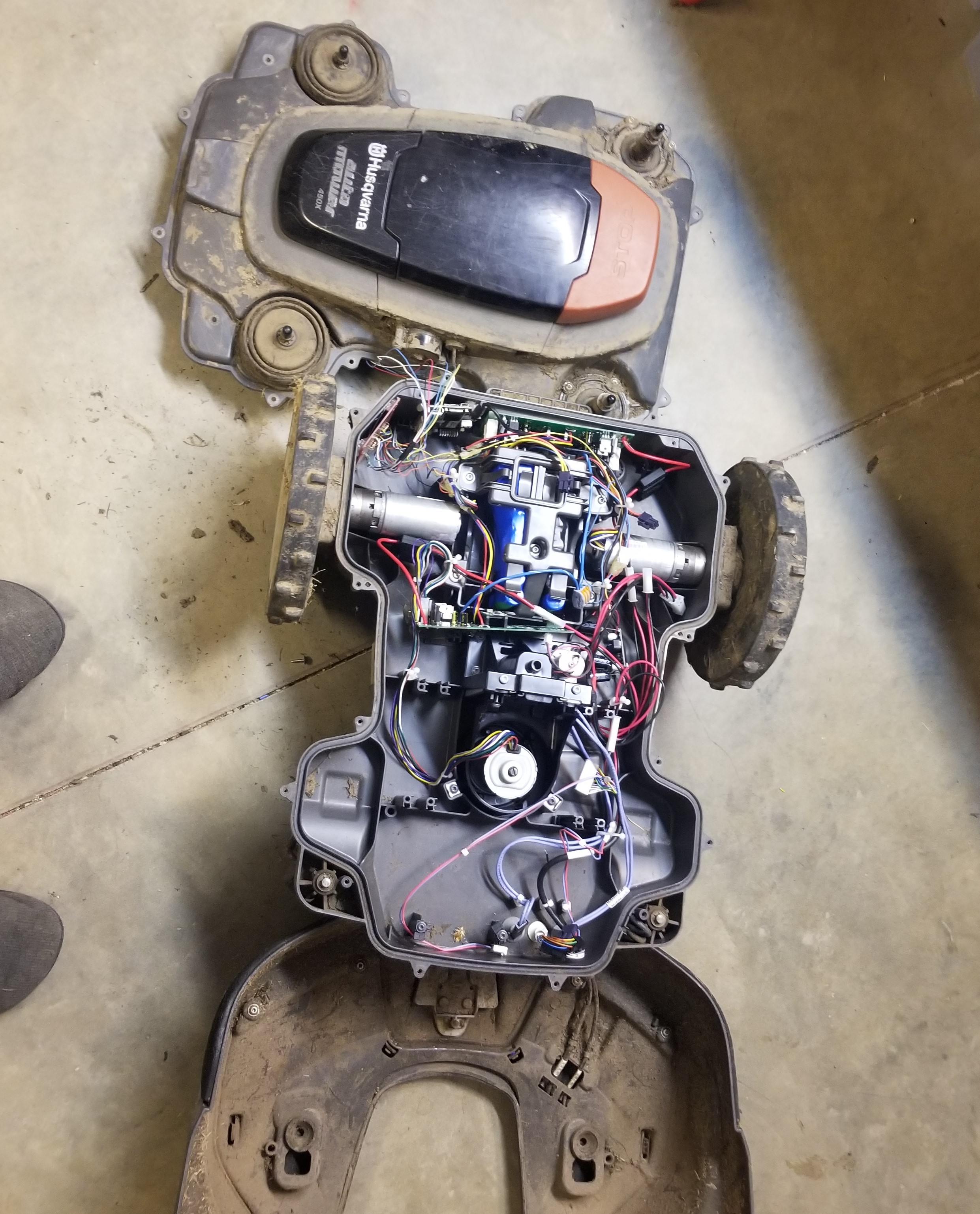
Tested with 3x brushed (non 3 phase) motors using https://github.com/simplefoc/Arduino-FOC-dcmotor - worked great but I did not test feedback, just that it could spin the motors. Off the top of my head there's only enough pico pins for 2x quadrature encoders.
Thank you:
Big thank you to https://github.com/ClemensElflein/ for creating the Open Mower project and his very well thought out 3 phase rp2040 servo amp code. His project inspired me to take the leap and make this happen. The original plan was use the openmower framework to control this servo amp, again - the amp plugs right into 450X automower drive motors, no hacking required. This board could(at least used to!) run (a version of?) the Xesc2040 servo amp code. Creating a firmware for this board that allows it to connect to openmower would be cool but I ended up writing a very simple mower controller instead.
SimpleFOC is absolutely brilliant. Can't recommend enough. If you are making bldc controllers they are a great place to start! (https://simplefoc.com/)
RP2040 / Pi Pico + Earle Philhower core (https://github.com/earlephilhower/arduino-pico) has been rock solid and a joy to work on.
Thanks to everyone who open sources their work - makes the world a better place. Hope my code helps you!
Plans/Stuff that's broken, rough order:
Next board iteration:
Cheers! -American Rework
| Qty | Value | Footprint | References |
|---|---|---|---|
| 18 | 010 | Resistor_SMD:R_0603_1608Metric | R1, R2, R3, R7, R10, R11, R12, R13, R15, R16, R17, R19, R23, R24, R25, R26 +2 |
| 12 | C3D10060A | Package_TO_SOT_THT:TO-220-2_Vertical | D7, D8, D9, D10, D11, D12, D13, D14, D15, D16, D17, D18 |
| 11 | Conn_01x02 | Connector_PinSocket_2.54mm:PinSocket_1x02_P2.54mm_Vertical | J6, J8, J9, J10, J11, J12, J13, J15, J16, J17, J18 |
| 8 | .1uF | Capacitor_SMD:C_0603_1608Metric | C2, C3, C4, C9, C15, C16, C17, C20 |
| 8 | Conn_01x01_Pin | Connector_PinHeader_2.54mm:PinHeader_1x01_P2.54mm_Vertical | J4, J5, J7, J19, J20, J23, J24, J25 |
| 8 | IRF540N | Package_TO_SOT_THT:TO-220-3_Vertical | Q1, Q2, Q3, Q4, Q5, Q6, Q11, Q12 |
| 6 | 100nF | Capacitor_SMD:C_0603_1608Metric | C1, C5, C6, C7, C19, C27 |
| 6 | 2k2 | Resistor_SMD:R_0603_1608Metric | R4, R5, R6, R20, R21, R22 |
| 6 | 470nF/16V | Capacitor_SMD:C_0603_1608Metric | C8, C10, C11, C18, C21, C23 |
| 6 | IRS2304 | Package_SO:SO-8_5.3x6.2mm_P1.27mm | U1, U2, U3, U6, U7, U9 |
| 6 | MTG Hole | MountingHole:MountingHole_2.2mm_M2 | FID2, FID2, FID2, FID2, FID2, FID2 |
| 6 | UF4007 | Diode_THT:D_DO-41_SOD81_P10.16mm_Horizontal | D1, D2, D3, D4, D5, D6 |
| 4 | 2.2uF/400v | Capacitor_THT:CP_Radial_D6.3mm_P2.50mm | C13, C14, C22, C28 |
| 4 | STGP10NC60H | Package_TO_SOT_THT:TO-220-3_Vertical | Q7, Q8, Q9, Q10 |
| 2 | 10uF/16V | Capacitor_SMD:C_0603_1608Metric | C24, C25 |
| 2 | 1mR | Resistor_SMD:R_2512_6332Metric | R14, R18 |
| 2 | 2.2uF/400V | Capacitor_THT:CP_Radial_D6.3mm_P2.50mm | C12, C26 |
| 2 | 874270842 | molex:CON_874270842 | J1, J22 |
| 2 | Conn_01x20_Pin | Connector_PinSocket_2.54mm:PinSocket_1x20_P2.54mm_Vertical | J2, J3 |
| 2 | INA180A4 | INA180:SOT95P280X145-5N | U4, U10 |
| 1 | 1N5817 | Diode_THT:D_DO-41_SOD81_P10.16mm_Horizontal | D20 |
| 1 | Pico | MCU_RaspberryPi_and_Boards:RPi_Pico_SMD_TH | U8 |
| 1 | XC6220B331MR | Package_TO_SOT_SMD:SOT-23-5 | U5 |
The 124 most common of 135 parts.


profdc9/ParanoiaBox
A standalone elliptic curve/AES file encryption and decryption device

baranovskiykonstantin/aquarium
Control the lighting and the heating of the aquarium.

JeyRunner/actonator
3D printable robot actuator with belt-driven gearbox and custom FOC driver board.

profdc9/NixieClock
A Nixie clock that uses IN-14 tubes and very generic components that can be easily sourced.
It measures 147.8 × 77 mm and has 4 copper layers, 1.6 mm thick.
135 parts, built around the STGP10NC60H, IRS2304PBF, XC6220B331MR and C3D10060A. The full list of its parts is on this page, with links to each part's symbol and footprint where PCBKit's library has them.
From the AmericanRework/Pico-2x-BLDC repository on GitHub, at the commit this page was made from: the board is PCB/2xBLDCPicoV3.kicad_pcb and its schematic PCB/2xBLDCPicoV3.kicad_sch. PCBKit opens the board in the browser, with nothing to install.
Its repository states no licence, so its author keeps all rights: ask AmericanRework before reusing the design.