2 layers20.3 × 48.3 mm
Rp2350a full
74th/rp2040-dev-board
治具には、中心から縦、横それぞれ 0.05 インチ単位で 0.200.50 インチ(1.27mm 単位で 5.08mm から 12.70mm)離れたとこにピンヘッダの固定用の穴が空いています。
45 parts21MIT

 74th/rp2040-dev-board21
治具には、中心から縦、横それぞれ 0.05 インチ単位で 0.200.50 インチ(1.27mm 単位で 5.08mm から 12.70mm)離れたとこにピンヘッダの固定用の穴が空いています。
Rp2350a testing is an open-source printed circuit board by 74th, from the 74th/rp2040-dev-board repository on GitHub, published under the MIT licence. It is a 2-layer board of 30.5 × 48.3 mm with 46 parts on 63 nets, routed with 558 tracks and 248 vias.
It is built around the RP2350A, W25Q32JVSSIQ and AMS1117, with the CH213K and SKRPABE010 among its other parts. Its parts include 19 capacitors, 11 resistors, 5 ICs, 2 connectors and 2 switches. It belongs with the RP2040 and RP2350 boards of this library.


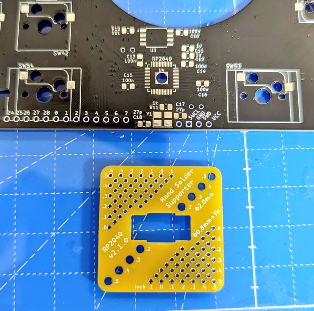
RP2040 を手はんだ実装するときに部品がずれないようにピンヘッダで固定する治具です。
この治具のおかげで、0.4mm ピッチの実装を簡単に行うことができます。
このディレクトリには、使い方の README(このファイル)と、KiCad での設計ファイルが含まれています。
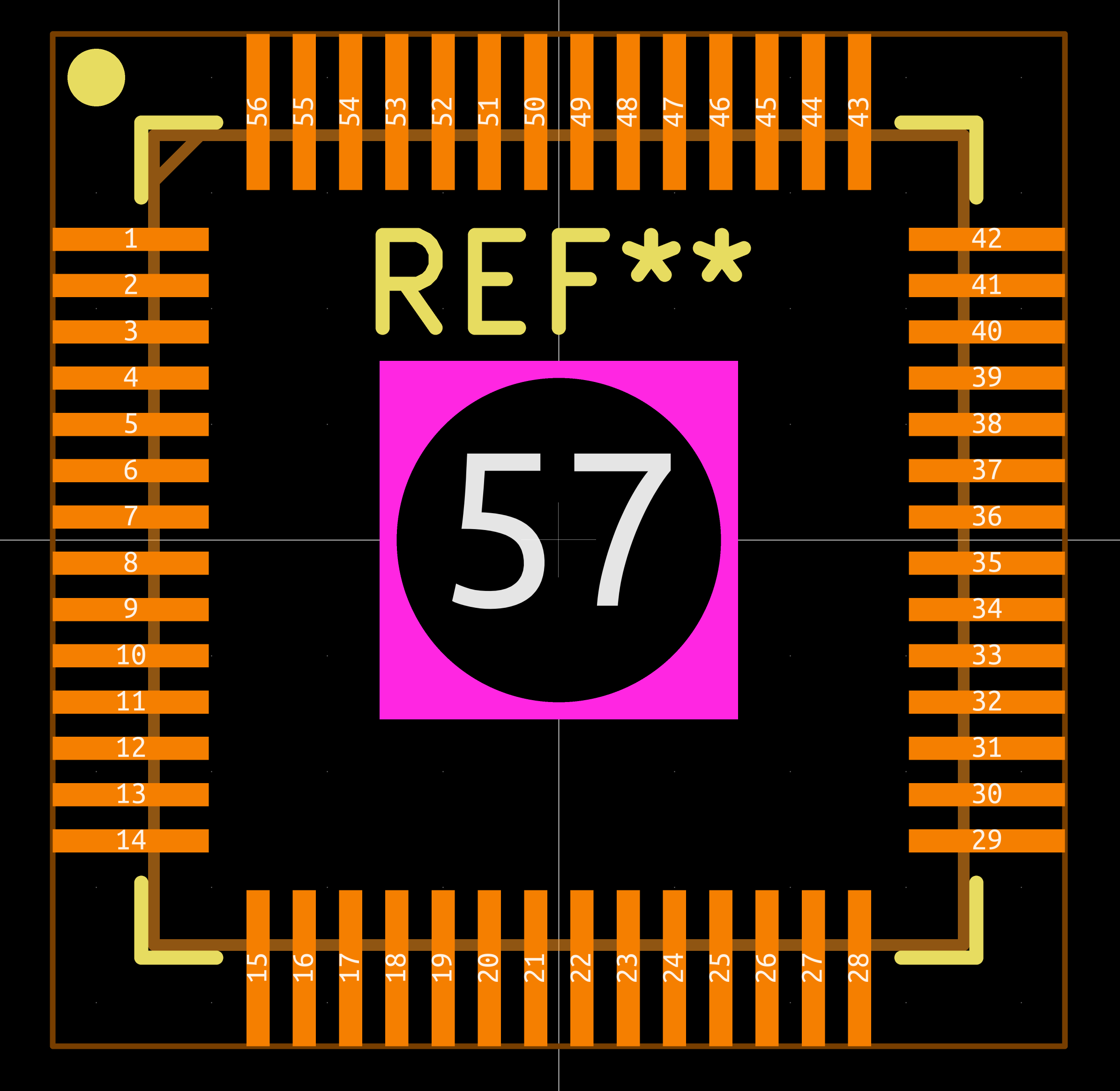
RP2040 のフットプリントは、このリポジトリにある rp2040-dev-board.pretty/RP2040_hand.kicad_mod を使用して、裏からサーマルパッドにはんだ付けできるものを利用してください。
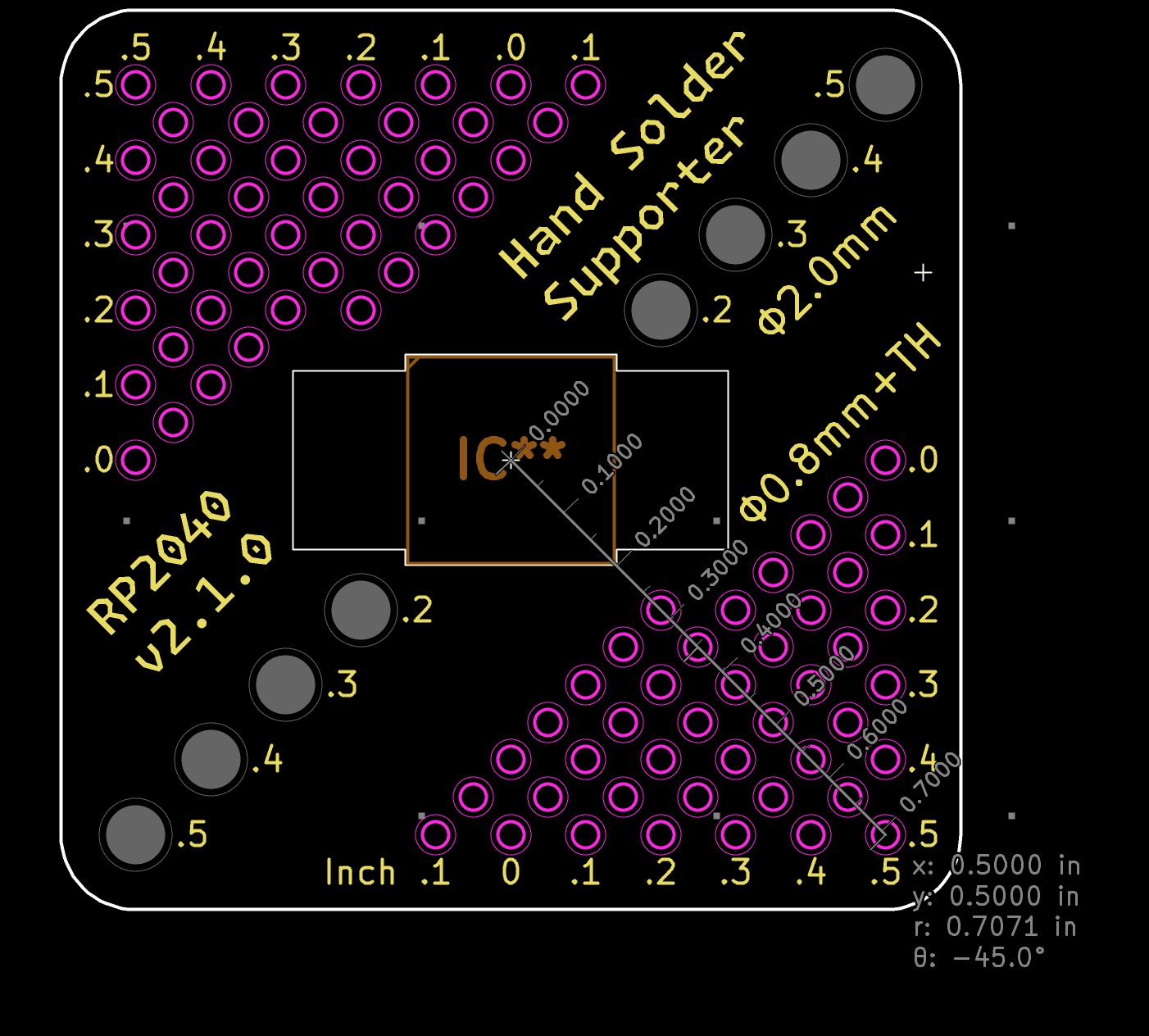
治具には、中心から縦、横それぞれ 0.05 インチ単位で 0.20~0.50 インチ(1.27mm 単位で 5.08mm から 12.70mm)離れたとこにピンヘッダの固定用の穴が空いています。
これらの穴を使うように、RP2040 のまわりに 4 点スルーホールを設けます。以下は 1 つの例です。
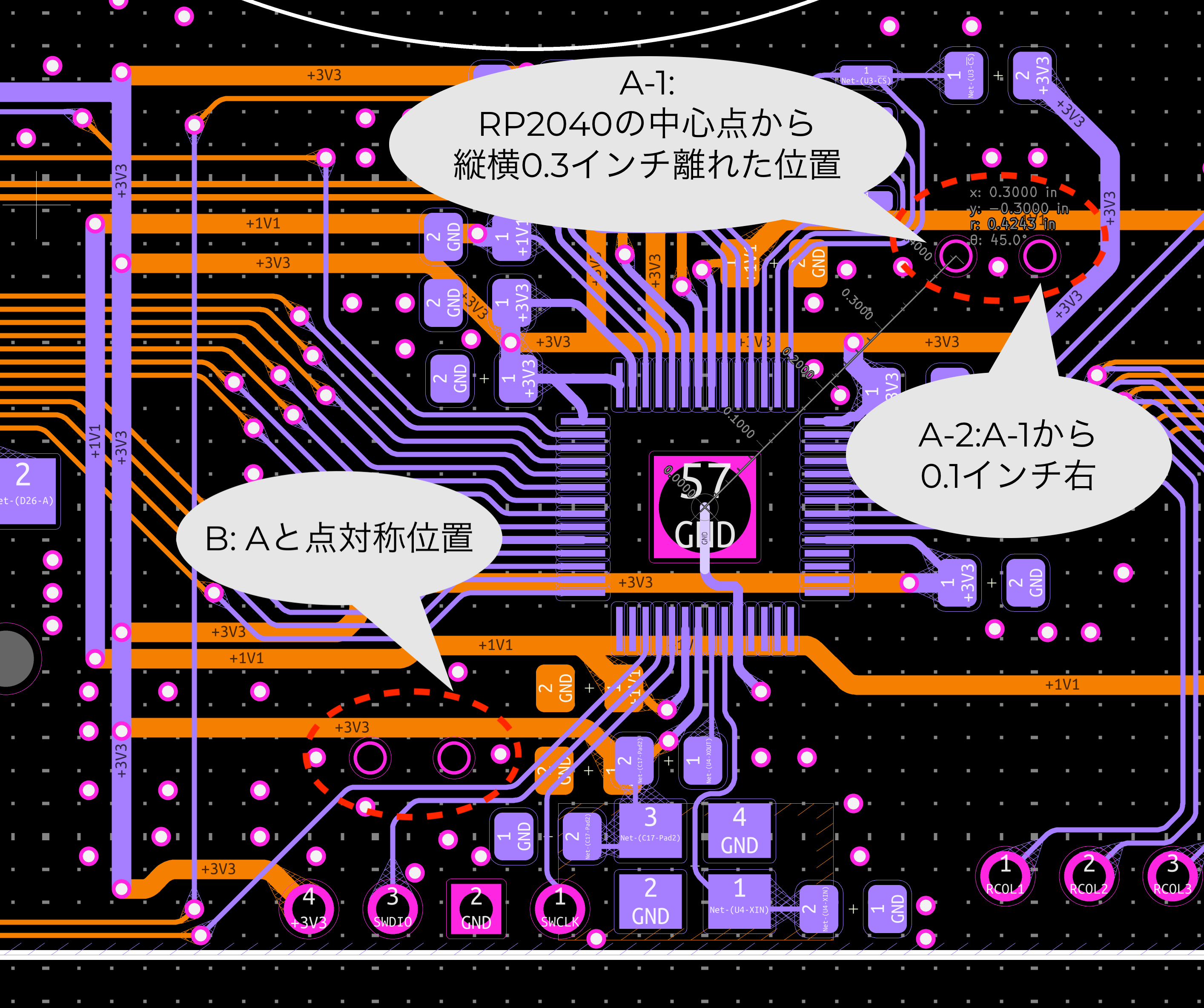
スルーホールの使用は以下のようにします。
実装時には 0.65mm ピンヘッダを通して配置し、RP2040 を治具にセットして、横側だけをはんだ付けします。この時にはブリッジは気にしないではんだ付けしてください。
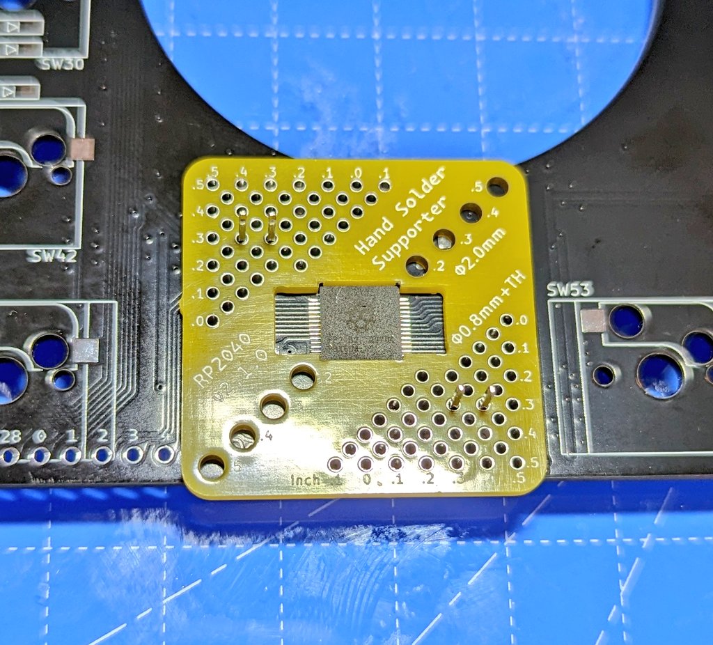
[!CAUTION] 治具を取り外す時にはかならず RP2040 を押さえつけながら行ってください。無理に外すと、治具が押さえつける力が強くて、パターンごと剥がれる場合があります。
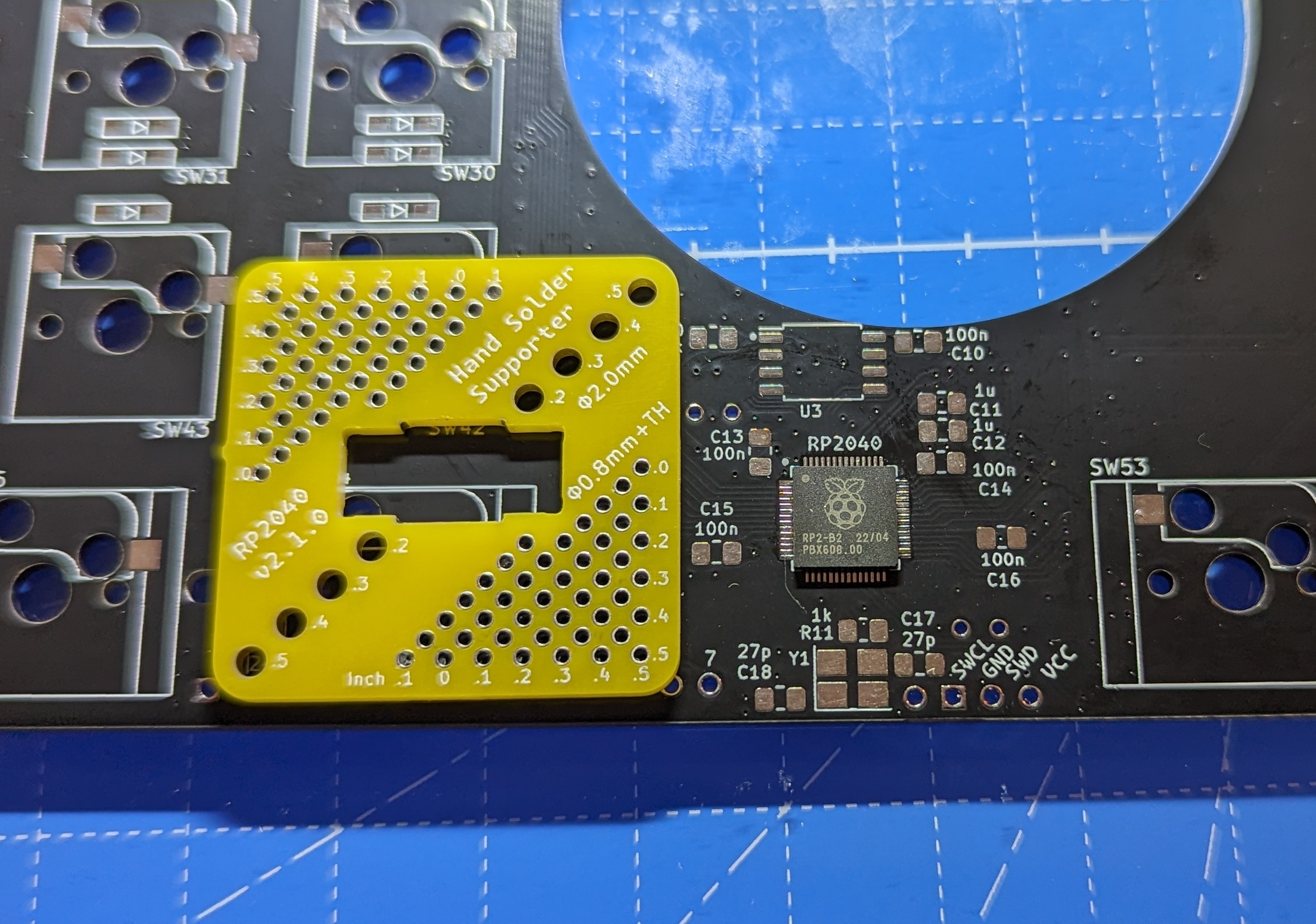
あとは、フラックスをながしてはんだごてを当てて余分なはんだを取り除いたり、残りのピンを実装したりしてください。
| Qty | Value | Footprint | References |
|---|---|---|---|
| 11 | 0.1u | 74th:Capacitor_0402_1005 | C3, C4, C9, C10, C11, C12, C13, C14, C15, C16, C17 |
| 3 | 4.7u | 74th:Capacitor_0402_1005_m | C5, C6, C8 |
| 2 | 10k | 74th:Register_0603_1608 | R5, R11 |
| 2 | 10p | 74th:Capacitor_0402_1005 | C18, C19 |
| 2 | 10u | 74th:Capacitor_0603_1608 | C1, C2 |
| 2 | 27 | 74th:Register_0603_1608 | R6, R7 |
| 2 | 5.1k | 74th:Register_0603_1608 | R1, R2 |
| 2 | Pin_19 | 74th:PinOut_Pin_19 | CH1, CH2 |
| 2 | SKRPABE010 | 74th:Switch_SKRPABE010_Pin-4 | SW1, SW2 |
| 1 | 0.1u | 74th:Capacitor_0603_1608 | C7 |
| 1 | 1 | 74th:Register_0603_1608 | R8 |
| 1 | 12M | 74th:Crystal_SMD_3225-4Pin_3.2x2.5mm_HandSoldering | Y1 |
| 1 | 1k | 74th:Register_0402_1005 | R10 |
| 1 | 1k | 74th:Register_0603_1608 | R4 |
| 1 | 200 | 74th:Register_0603_1608 | R3 |
| 1 | 3.3u | 74th:Inductor_4.1x4.5mm_testing | L1 |
| 1 | 33 | 74th:Register_0603_1608 | R9 |
| 1 | AMS1117 | 74th:Package_SOT-89-3 | U3 |
| 1 | Blue | 74th:LED_0805_2012 | D1 |
| 1 | CH213K | 74th:Package_SOT-23 | U1 |
| 1 | LOGO | 74th:Logo_74th_7.5mm | MISC-ICON |
| 1 | RP2350A | 74th:Package_QFN-60-1EP_7x7mm_P0.4mm_EP3.4x3.4mm_hand | U5 |
| 1 | SWD_10Pin_MCU-Side | 74th:Connector_HalfPinHeader_SWD | J2 |
| 1 | SWD_3Pin | 74th:PinOut_Pin_3_2GND | CH3 |
| 1 | TLV74311 | 74th:Package_SOT-23-5 | U2 |
| 1 | USB2.0-C_SMT | 74th:Connector_USB-C-Receptacle_SMT_12-Pin_Simple | J1 |
| 1 | W25Q32JVSS | 74th:Package_USON-8_3x4mm_P0.8 | U4 |
74th/rp2040-dev-board
治具には、中心から縦、横それぞれ 0.05 インチ単位で 0.200.50 インチ(1.27mm 単位で 5.08mm から 12.70mm)離れたとこにピンヘッダの固定用の穴が空いています。

74th/rp2040-dev-board
治具には、中心から縦、横それぞれ 0.05 インチ単位で 0.200.50 インチ(1.27mm 単位で 5.08mm から 12.70mm)離れたとこにピンヘッダの固定用の穴が空いています。

74th/rp2040-dev-board
治具には、中心から縦、横それぞれ 0.05 インチ単位で 0.200.50 インチ(1.27mm 単位で 5.08mm から 12.70mm)離れたとこにピンヘッダの固定用の穴が空いています。

hazy2go/gb-link-usb
Game Boy (DMG) link port to USB-C PC adapter: printer emulation, PC link, online link play. Sister project of the WiFi Game Boy cart.


smartbank-inc/Board43
Board43 is an RP2350A-based microcontroller development board. Flash PicoRuby or your favorite firmware and start hacking.

konrad-bode/SummerSchool_25
This repository contains the KiCad hardware design for the HeiChips 2025 SummerSchool FPGA Carrier Board, designed to interface with the custom tapeout FPGA chip from the HeiChips 2025 Tapeout Repository.
It measures 30.5 × 48.3 mm and has 2 copper layers, 1.6 mm thick.
46 parts, built around the RP2350A, W25Q32JVSSIQ, AMS1117 and CH213K. The full list of its parts is on this page, with links to each part's symbol and footprint where PCBKit's library has them.
From the 74th/rp2040-dev-board repository on GitHub, at the commit this page was made from: the board is rp2350a-testing/rp2350a-testing.kicad_pcb and its schematic rp2040-large/rp2040-large.kicad_sch. PCBKit opens the board in the browser, with nothing to install.
Its repository publishes it under the MIT licence: you may reuse it on that licence's terms (keep the author's notice, and for a copyleft licence share your changes alike).