2 layers34.3 × 39.4 mm

 74th/74th-oshw-projects1
74th のPCBデータを公開しているプロジェクト
Wire connect checker is an open-source printed circuit board by 74th, from the 74th/74th-oshw-projects repository on GitHub, published under the MIT licence. It is a 2-layer board of 53.5 × 69.5 mm with 73 parts on 67 nets, routed with 431 tracks and 186 vias.
It is built around the CH32V003F4P6, AMS1117 and CH213K. Its parts include 23 resistors, 21 diodes, 10 transistors, 3 capacitors and 3 ICs. It belongs with the RISC-V boards of this library.


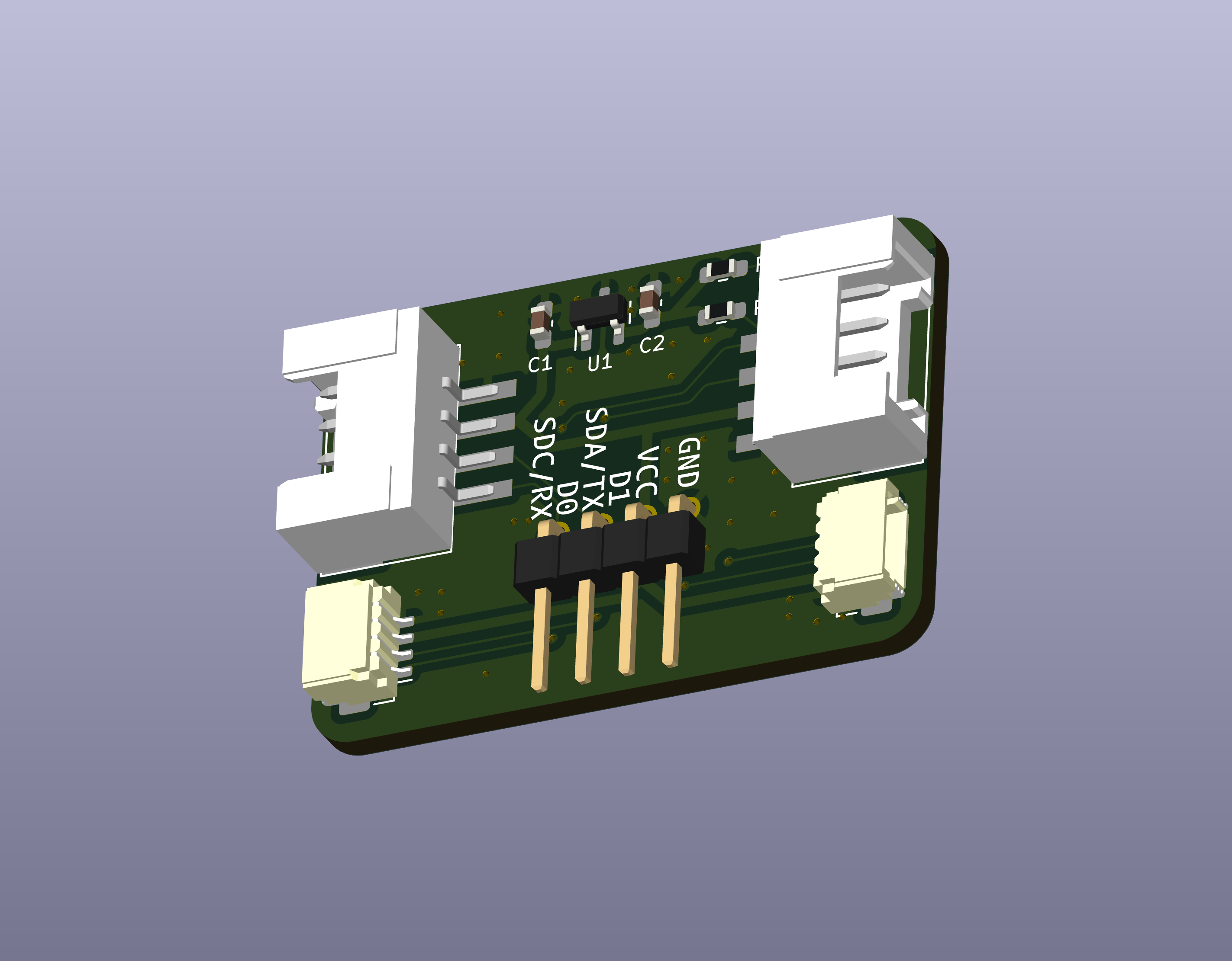
| Reference | Name | Quantity |
|---|---|---|
| CH1,CH2 | HY2.0 Socket SMD 4Pin (Grove) - Grove | 2 |
| CH4,CH5 | SH1.0 Socket SMD 4Pin (Qwiic) - Qwiic | 2 |
| C1,C2 | Capacitor 0603 100nF | 2 |
| R1,R2 | Register 0603 1kΩ | 2 |
| U1 | Regulator 3.3V SOT-23 AP7333-33SAG | 1 |
| Qty | Value | Footprint | References |
|---|---|---|---|
| 16 | 10k | 74th:Register_0805_2012 | R3, R4, R6, R7, R8, R9, R10, R14, R16, R17, R18, R19, R20, R21, R22, R23 |
| 16 | BLUE | 74th:LED_0805_2012 | D2, D3, D4, D5, D6, D7, D8, D12, D14, D15, D16, D17, D18, D19, D20, D21 |
| 10 | 2N7002 | 74th:Package_SOT-23 | Q1, Q2, Q3, Q4, Q5, Q6, Q7, Q8, Q9, Q10 |
| 4 | 1k | 74th:Register_0805_2012 | R11, R12, R13, R15 |
| 4 | YELLOW | 74th:LED_0805_2012 | D9, D10, D11, D13 |
| 3 | 5.1k | 74th:Register_0805_2012 | R1, R2, R5 |
| 2 | 1u | 74th:Capacitor_0805_2012 | C1, C2 |
| 2 | BoxPinHeader2x3 | 74th:Connector_BoxPinHeader_2x03_P1.27mm | CH2, CH9 |
| 2 | BoxPinHeader2x5 | 74th:Connector_BoxPinHeader_2x05_P1.27mm | CH4, CH10 |
| 2 | HY2.0 | 74th:Connector_HY-2.0_TH-Vertical_4Pin | CH3, CH7 |
| 2 | SH1.0 | 74th:Connector_SH-1.0_SMD_4Pin | CH1, CH6 |
| 2 | XH2.5 | Connector_JST:JST_XH_B4B-XH-AM_1x04_P2.50mm_Vertical | CH5, CH8 |
| 1 | 100n | 74th:Capacitor_0805_2012 | C3 |
| 1 | AMS1117 | 74th:Package_SOT-89-3 | U3 |
| 1 | CH213K | 74th:Package_SOT-23 | U4 |
| 1 | CH32V003F4P6 | 74th:Package_TSSOP-20_4.4x6.5mm_P0.65mm | U1 |
| 1 | LOGO | $74th:74th-7.5mm | MISC-ICON |
| 1 | RED | 74th:LED_0805_2012 | D1 |
| 1 | SWD | 74th:PinOut_Pin_3_3GND | CH11 |
| 1 | USB2.0-C_SMT | 74th:Connector_USB-C-Receptacle_SMT_12-Pin_Simple | J1 |


74th/rp2040-dev-board
治具には、中心から縦、横それぞれ 0.05 インチ単位で 0.200.50 インチ(1.27mm 単位で 5.08mm から 12.70mm)離れたとこにピンヘッダの固定用の穴が空いています。


openwch/ch334
Share the schematic and layout (KiCad) for DIY USB2.0 4-PORTS HUB with CH334U


It measures 53.5 × 69.5 mm and has 2 copper layers, 1.6 mm thick.
73 parts, built around the CH32V003F4P6, AMS1117 and CH213K. The full list of its parts is on this page, with links to each part's symbol and footprint where PCBKit's library has them.
From the 74th/74th-oshw-projects repository on GitHub, at the commit this page was made from: the board is 74TH-G057-diy_cable_checker/wire_connect_checker.kicad_pcb. PCBKit opens the board in the browser, with nothing to install.
Its repository publishes it under the MIT licence: you may reuse it on that licence's terms (keep the author's notice, and for a copyleft licence share your changes alike).