4 layers80 × 50 mm

 xuan25/SlimeVR-Tracker-HW5
Hardware design of my SlimeVR Tracker
SlimeVR Tracker is an open-source printed circuit board by xuan25, from the xuan25/SlimeVR-Tracker-HW repository on GitHub, published under the MIT licence. It is a 2-layer board of 30 × 30 mm with 61 parts on 67 nets, routed with 452 tracks and 87 vias.
It is built around the ESP32-C3-MINI-1, TPS62162DSG and BNO08X, with the BQ24075RGT and GT-USB-7010ASV among its other parts. Its parts include 21 resistors, 12 capacitors, 4 ICs, 3 diodes and 3 connectors. It belongs with the ESP32 and RISC-V boards of this library.


A design of SlimeVR Tracker by Xuan25
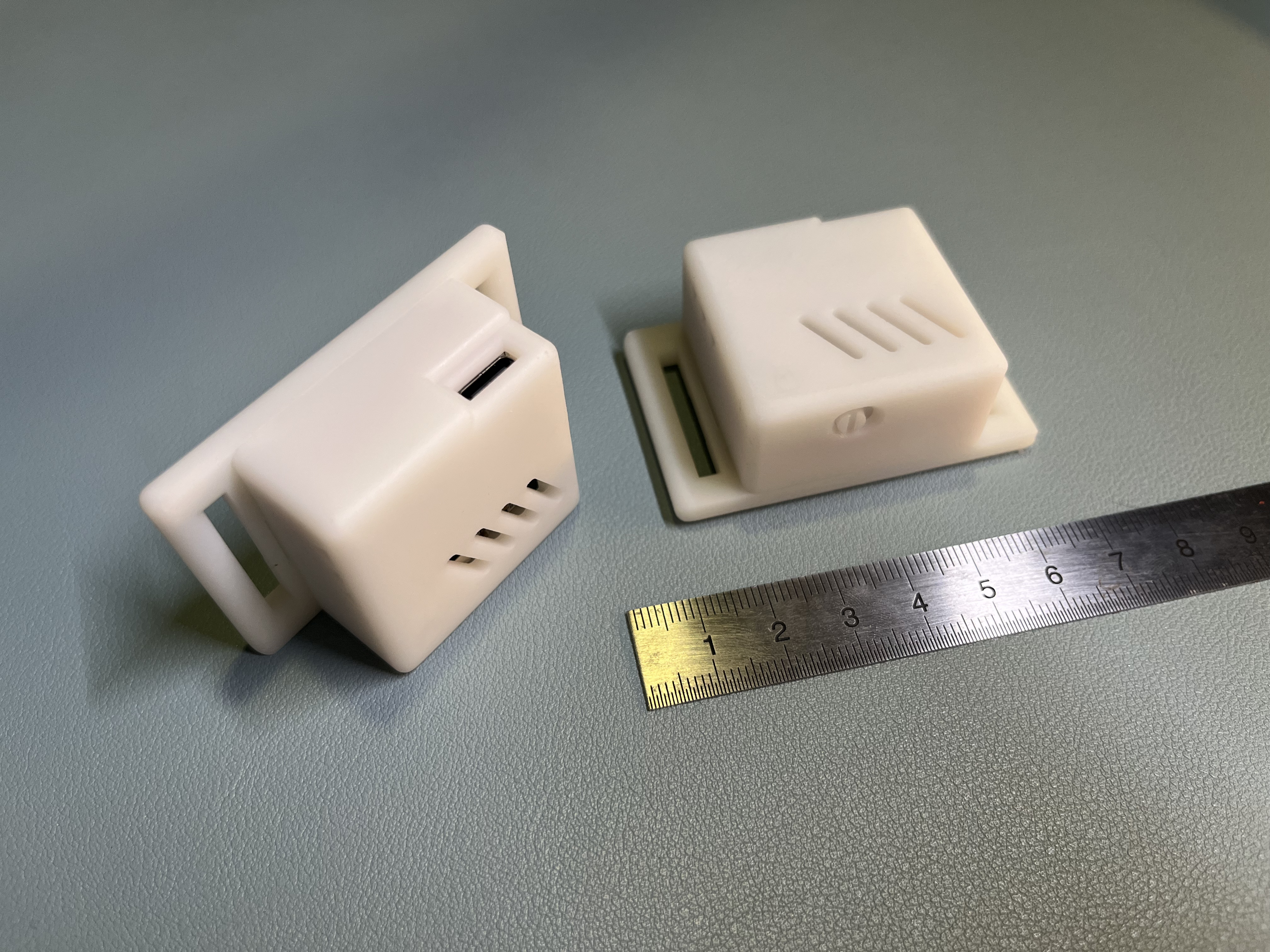
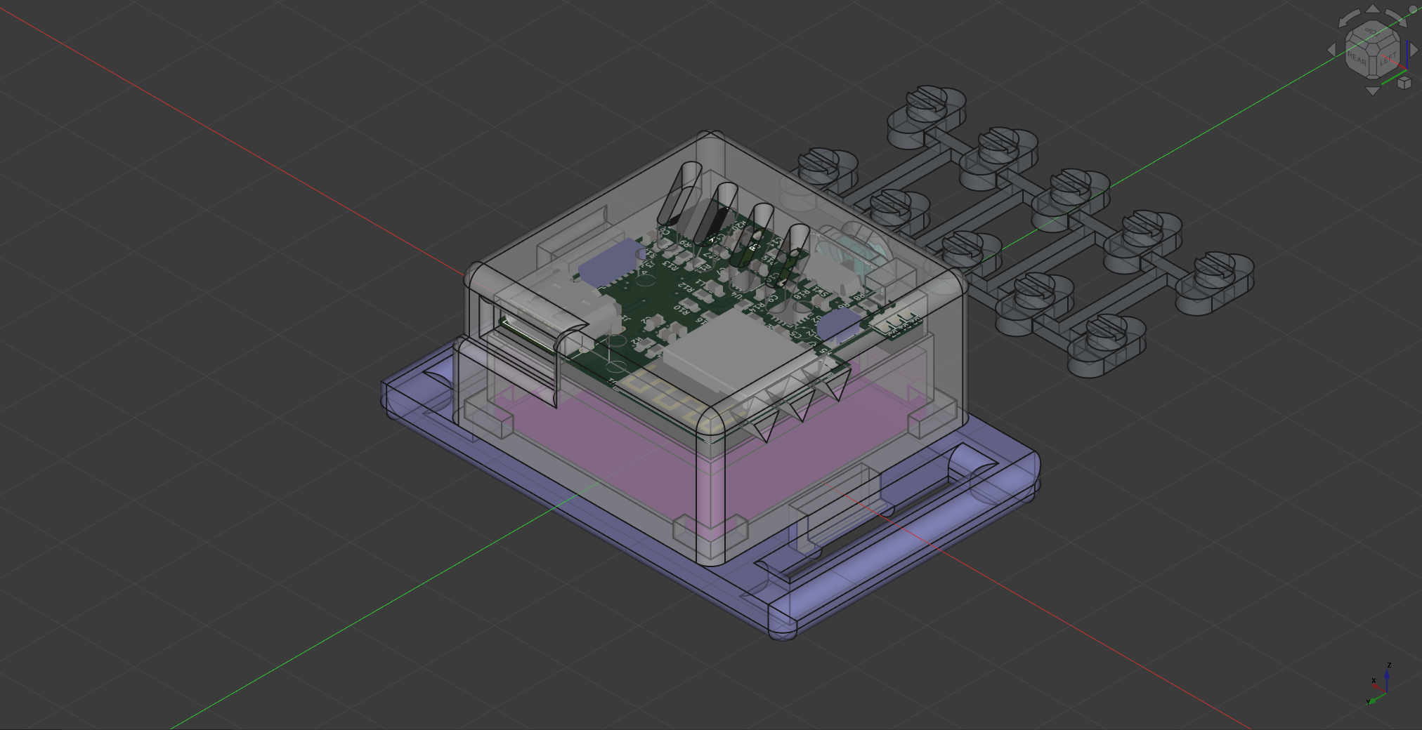
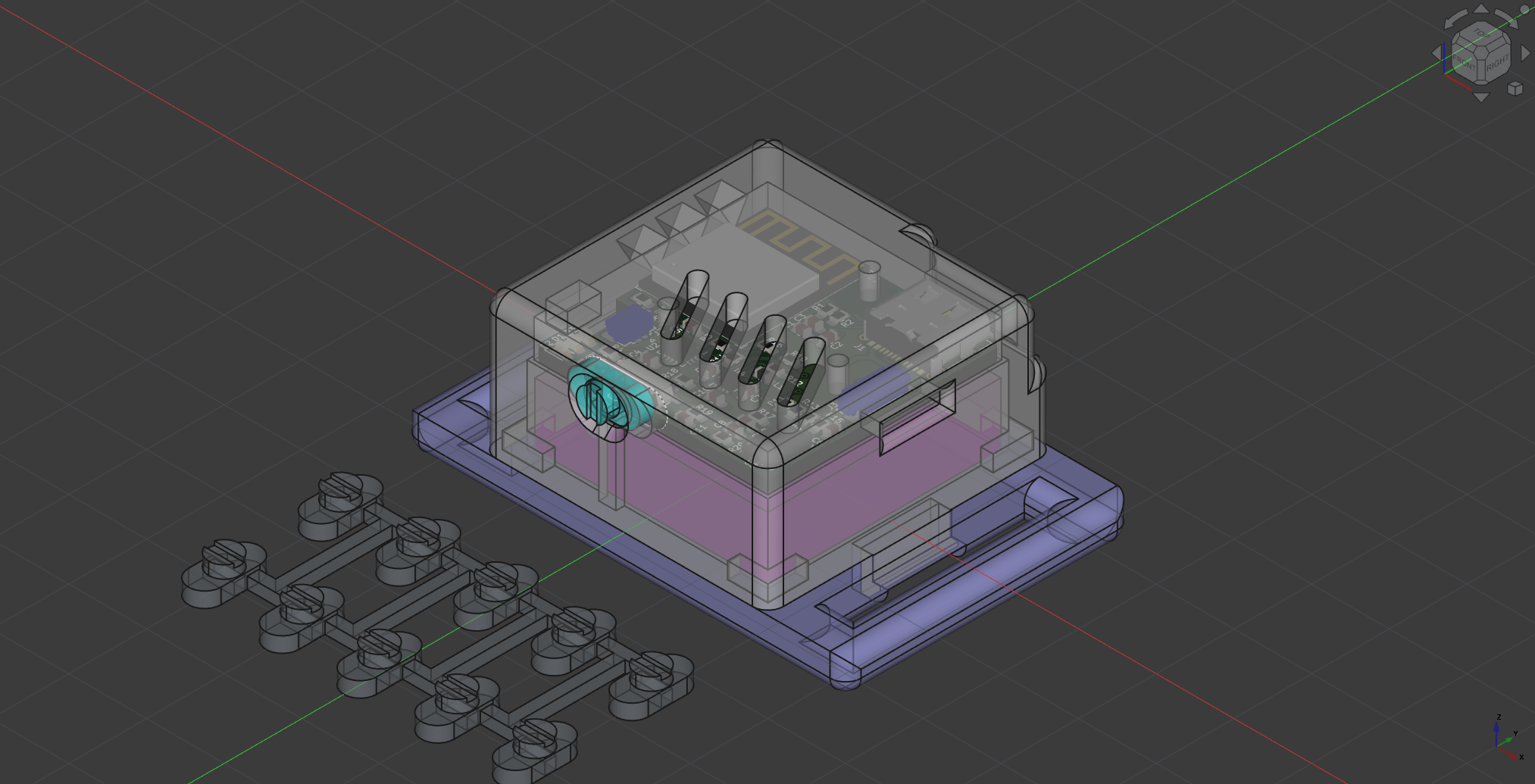
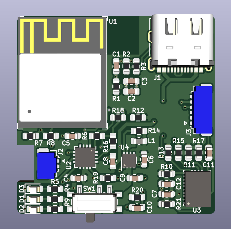
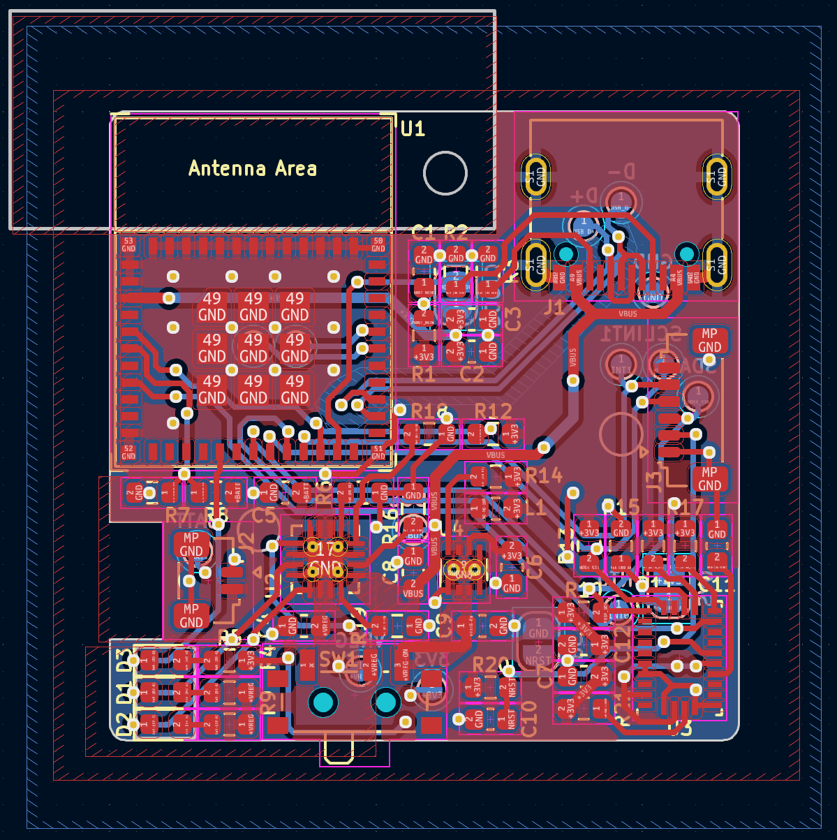
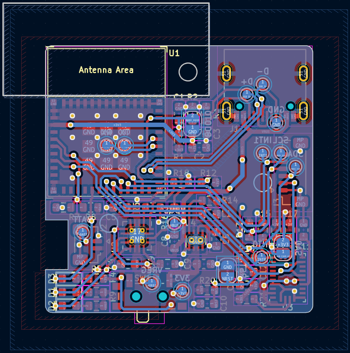
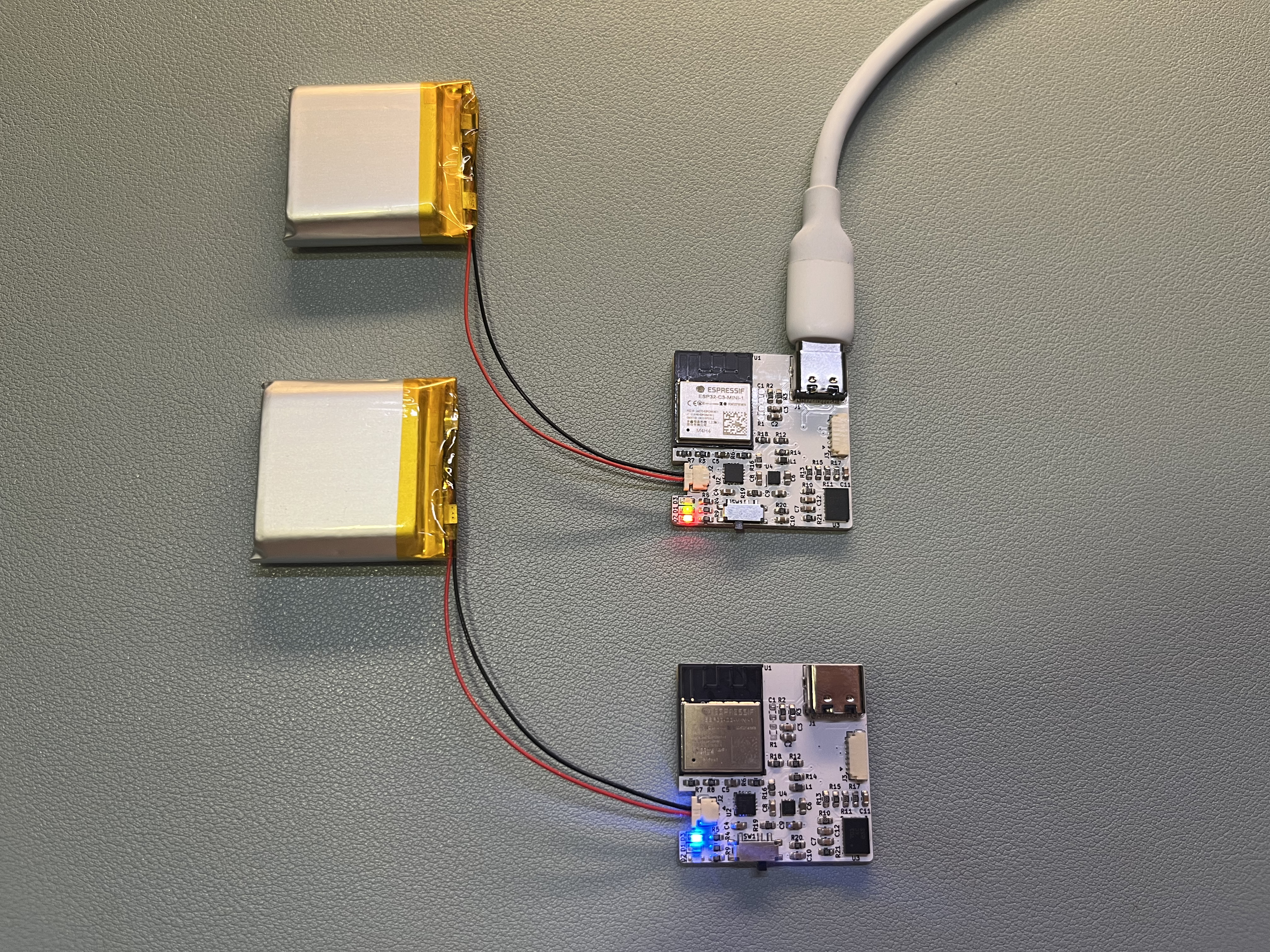
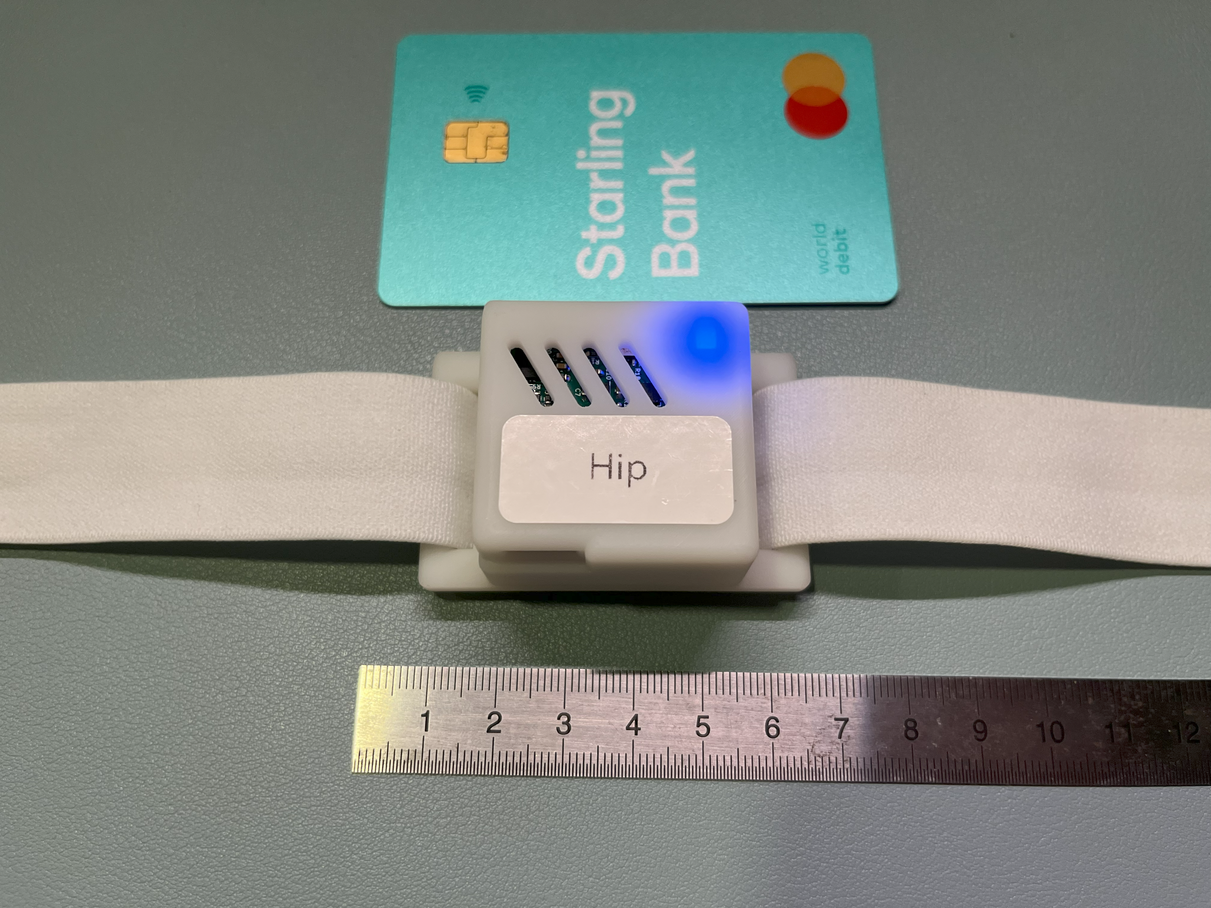
See the latest release for the production files:
PCB-gbr.zip: Gerber files for PCB productionPCB-BOM.csv: Bill of Materials for PCB assemblyPCB-assembly-scale4.pdf: Component reference for PCB assembly3DP.zip: STL model files for 3D printingIn addition to the materials listed in the BOM for PCB assembly, you will also need:
700mAh 803030 3.7V Lithium Polymer Battery x1 (the battery)SSUH-003T-P0.15 x2 (socket contacts for the battery)SUHR-02V-S-B x1 (socket contact housing)28AWG FEP Wire x2 (wires connect the battery and the PCB)2mm thick EVA Foam Craft Sheets x1 (spacer between the battery and the PCB)25mm width Elastic Band + Accessoriesplus:
138°C Low Temperature Soldering PasteSolder FluxPCB Cleaning Solution + Brush8mm Polyimide Tape + 30mm Polyimide Tape (for battery breakout board insulation)Required tools include:
ENGINEER PAD-11 Handy Crimp Tool (crimp battery connectors)Hotplate for SMD SolderingSoldering IronTweezersDiagonal cutting plier + Sandpaper (3D printing post-processing)Light and MagnifierYou may want to update the following parameters in the Case design Spreadsheet to match the performance of your 3D printer and material.
| Qty | Value | Footprint | References |
|---|---|---|---|
| 7 | 10k | Resistor_SMD:R_0603_1608Metric | R1, R6, R7, R12, R15, R20, R21 |
| 5 | 0.1u | Capacitor_SMD:C_0603_1608Metric | C1, C3, C7, C11, C12 |
| 4 | 2.2k | Resistor_SMD:R_0603_1608Metric | R10, R11, R13, R17 |
| 3 | 1.5k | Resistor_SMD:R_0603_1608Metric | R4, R5, R9 |
| 2 | 10u | Capacitor_SMD:C_0603_1608Metric | C2, C9 |
| 2 | 1u | Capacitor_SMD:C_0603_1608Metric | C8, C10 |
| 2 | 4.7u | Capacitor_SMD:C_0603_1608Metric | C4, C5 |
| 2 | 5.1k | Resistor_SMD:R_0603_1608Metric | R2, R3 |
| 1 | 1.8k | Resistor_SMD:R_0603_1608Metric | R18 |
| 1 | 100k | Resistor_SMD:R_0603_1608Metric | R14 |
| 1 | 2.2u | Inductor_SMD:L_0603_1608Metric | L1 |
| 1 | 22u | Capacitor_SMD:C_0603_1608Metric | C6 |
| 1 | 3.3k | Resistor_SMD:R_0603_1608Metric | R19 |
| 1 | 30k | Resistor_SMD:R_0603_1608Metric | R16 |
| 1 | 3V3 | TestPoint:TestPoint_Pad_D1.0mm | TP10 |
| 1 | 40.2k | Resistor_SMD:R_0603_1608Metric | R8 |
| 1 | B | LED_SMD:LED_0603_1608Metric | D3 |
| 1 | BATT | TestPoint:TestPoint_Pad_D1.0mm | TP12 |
| 1 | BNO08X | Package_LGA:LGA-28_5.2x3.8mm_P0.5mm | U3 |
| 1 | BOOT0 | Jumper:SolderJumper-2_P1.3mm_Open_RoundedPad1.0x1.5mm | JP1 |
| 1 | BQ24075RGT | Package_DFN_QFN:VQFN-16-1EP_3x3mm_P0.5mm_EP1.68x1.68mm_ThermalVias | U2 |
| 1 | D+ | TestPoint:TestPoint_Pad_D1.0mm | TP3 |
| 1 | D- | TestPoint:TestPoint_Pad_D1.0mm | TP4 |
| 1 | ESP32-C3-MINI-1 | PCM_Espressif:ESP32-C3-MINI-1 | U1 |
| 1 | G | LED_SMD:LED_0603_1608Metric | D1 |
| 1 | GND | TestPoint:TestPoint_Pad_D1.0mm | TP5 |
| 1 | GT-USB-7010ASV | Connector_USB:USB_C_Receptacle_G-Switch_GT-USB-7010ASV | J1 |
| 1 | INT0 | TestPoint:TestPoint_Pad_D1.0mm | TP9 |
| 1 | INT1 | TestPoint:TestPoint_Pad_D1.0mm | TP2 |
| 1 | R | LED_SMD:LED_0603_1608Metric | D2 |
| 1 | RST | Jumper:SolderJumper-2_P1.3mm_Open_RoundedPad1.0x1.5mm | JP2 |
| 1 | RX | TestPoint:TestPoint_Pad_D1.0mm | TP6 |
| 1 | SA0 | Jumper:SolderJumper-2_P1.3mm_Open_RoundedPad1.0x1.5mm | JP3 |
| 1 | SCL | TestPoint:TestPoint_Pad_D1.0mm | TP1 |
| 1 | SDA | TestPoint:TestPoint_Pad_D1.0mm | TP8 |
| 1 | SUR_SM02B-SURS-TF | Connector_JST:JST_SUR_SM02B-SURS-TF_1x02-1MP_P0.80mm_Horizontal | J2 |
| 1 | SUR_SM06B-SURS-TF | Connector_JST:JST_SUR_SM06B-SURS-TF_1x06-1MP_P0.80mm_Horizontal | J3 |
| 1 | SW_SPDT_PCM12 | Button_Switch_SMD:SW_SPDT_PCM12 | SW1 |
| 1 | TPS62162DSG | Package_SON:WSON-8-1EP_2x2mm_P0.5mm_EP0.9x1.6mm_ThermalVias | U4 |
| 1 | TX | TestPoint:TestPoint_Pad_D1.0mm | TP7 |
| 1 | VBUS | TestPoint:TestPoint_Pad_D1.0mm | TP11 |
| 1 | VREG | TestPoint:TestPoint_Pad_D1.0mm | TP13 |


thiagoeustakio/bioin_tacto
This repository include all design files and source code for the sensing module describe in "BioIn-Tacto: A compliant multi-modal tactile sensing module for robotic tasks".

R-Josef/SlimeVR-Hardware
This is a SlimeVR hardware project, including a PCB file and case models.


It measures 30 × 30 mm and has 2 copper layers, 1.6 mm thick.
61 parts, built around the ESP32-C3-MINI-1, TPS62162DSG, BNO08X and BQ24075RGT. The full list of its parts is on this page, with links to each part's symbol and footprint where PCBKit's library has them.
From the xuan25/SlimeVR-Tracker-HW repository on GitHub, at the commit this page was made from: the board is PCB/SlimeVR-Tracker.kicad_pcb and its schematic PCB/SlimeVR-Tracker.kicad_sch. PCBKit opens the board in the browser, with nothing to install.
Its repository publishes it under the MIT licence: you may reuse it on that licence's terms (keep the author's notice, and for a copyleft licence share your changes alike).