

2 layers37 × 37 mm

 R-Josef/SlimeVR-Hardware2
This is a SlimeVR hardware project, including a PCB file and case models.
SlimeVR is an open-source printed circuit board by R-Josef, from the R-Josef/SlimeVR-Hardware repository on GitHub. It is a 2-layer board of 30 × 60 mm with 10 parts on 28 nets, routed with 117 tracks and 22 vias.
It is built around the BNO08X and TP4056. Its parts include 3 ICs, 2 diodes, 1 resistor and 1 connector. It belongs with the ESP8266 boards of this library.
This is a SlimeVR hardware project, including a PCB file and case models.
First, prepare the following materials:
| Designator | Materials | Quantity | Comment |
|---|---|---|---|
| U1 | ESP8266-D1-Mini | 1 | Also called WeMos D1 Mini, Type-C is recommended |
| U2 | BNO08X | 1 | IMU, BNO085/BNO080 |
| U3 | TP4056 | 1 | TP4056, Type-C is recommended |
| D1, D2 | 1N5817 | 2 | Charge diodes |
| R1 | 180k 1/4W resistor | 1 | Battery sense |
| SM1 | MSK-12D19 (1P2T) | 1 | Toggle Switch |
| BT1 | Molex PicoBlade connector 1x2p 1.25mm vertical | 1 | This is a common connector type for lithium batteries |
| 3.7v lithium battery | 1 | 102540mm (102540) is recommended | |
| J1 | Molex PicoBlade connector 1x5p 1.25mm vertical | 1 | Auxiliary tracker connector (this is an optional) |
| JP1 | PinHeader 1x2p 1.27mm vertical | 1 | Pinheader for jumper (this is an optional) |
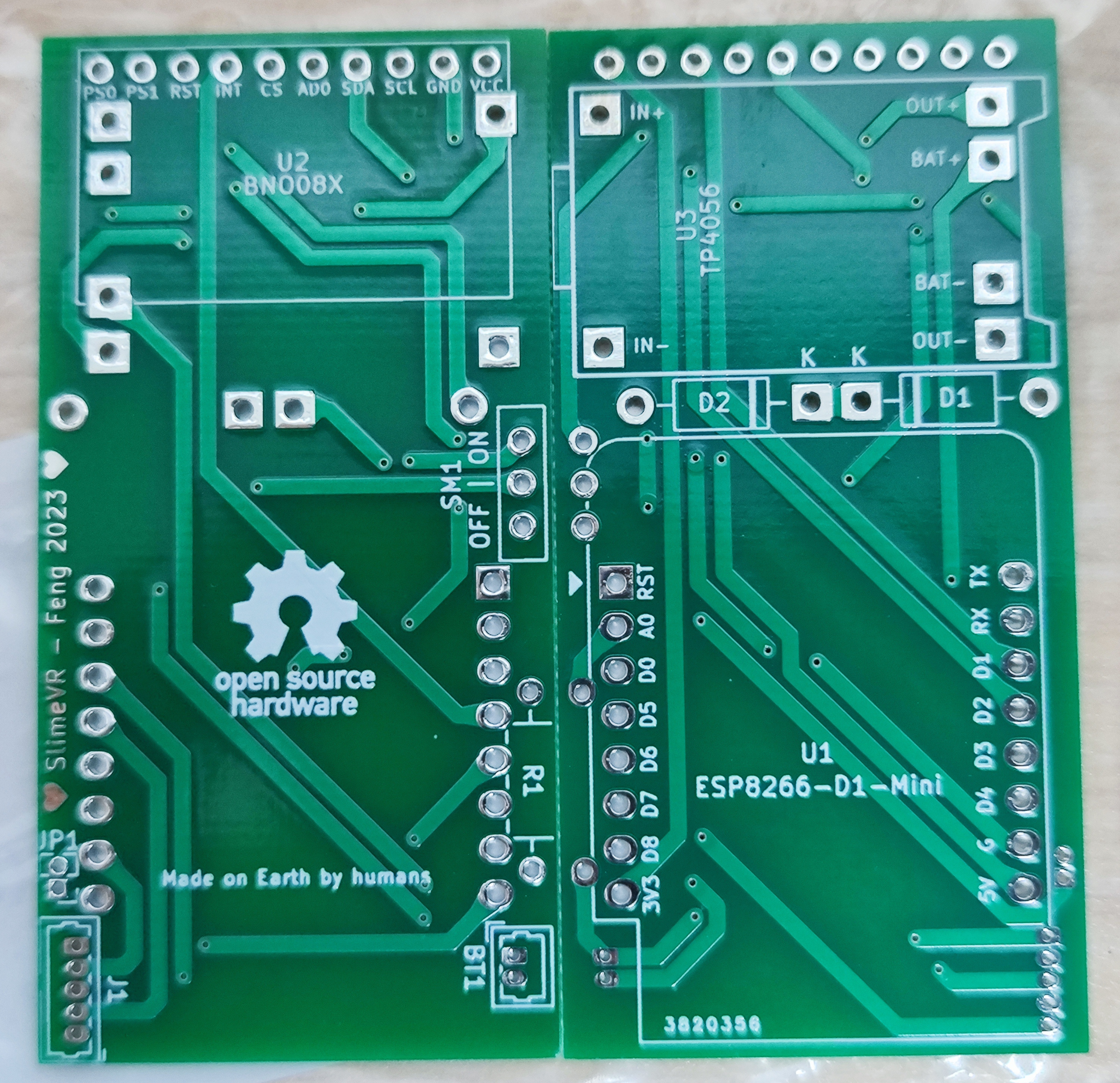
Then you need to download the Gerber.zip file, provide this file to the PCB manufacturer to make your boards.
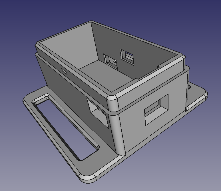
Finally, download the Case.stl file and Lip.stl file and use it for 3d printing, you will get cases.
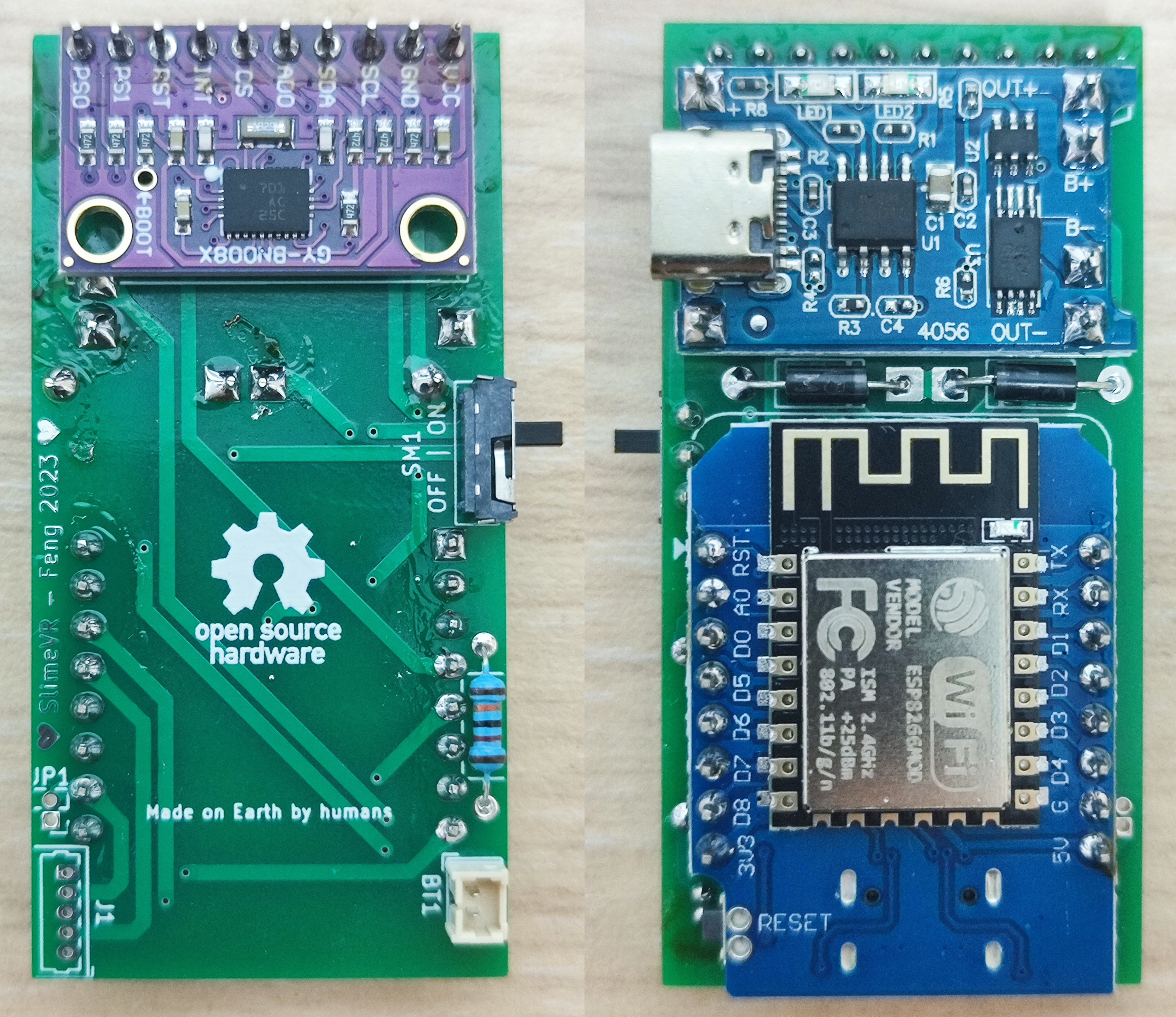
Solder the parts that need to be soldered to the PCB, Your board should now look like this:
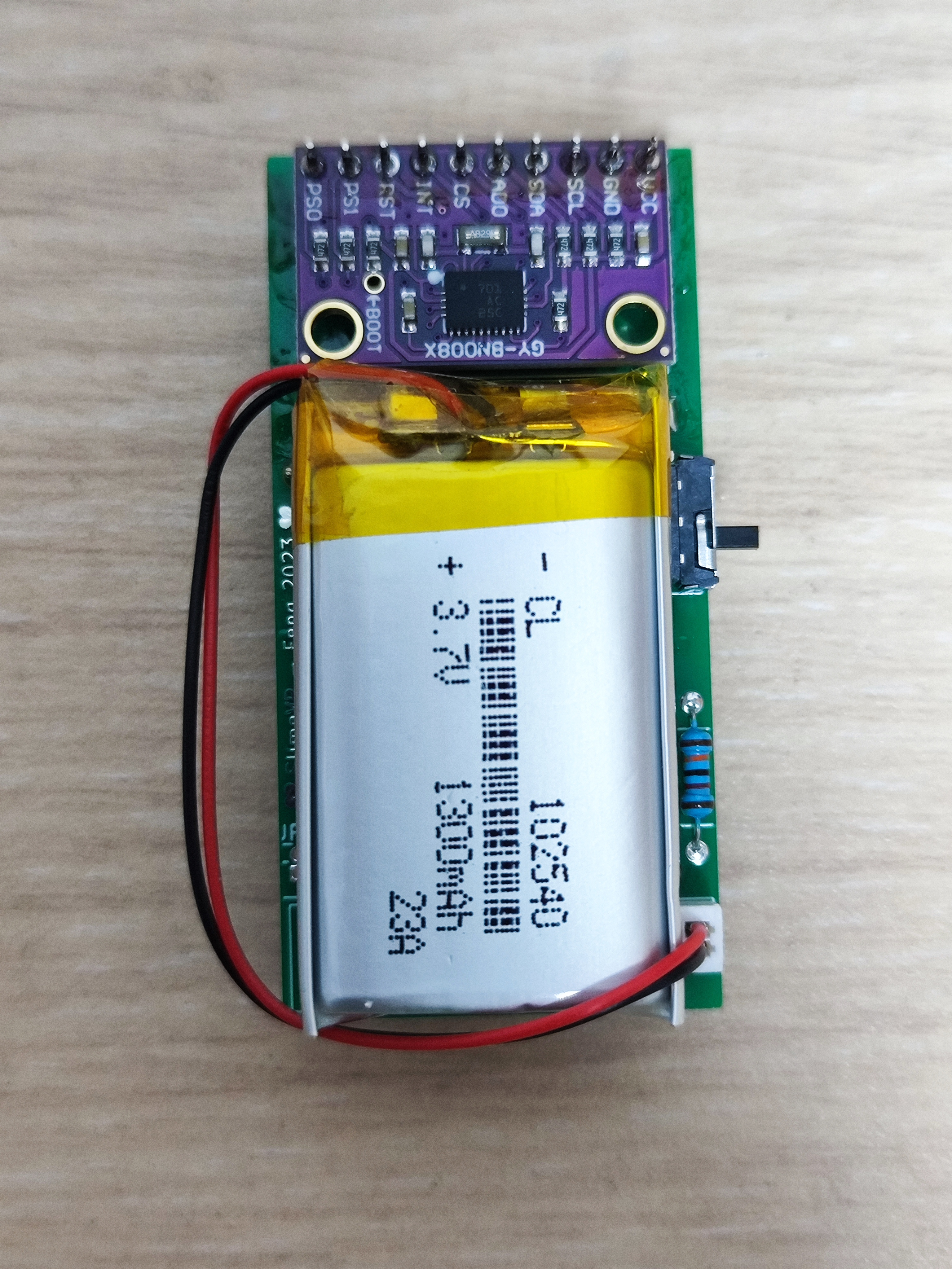
You can now connect the D1 Mini to your computer with a USB cable, and then burn the firmware. If everything is ok, you can plug the lithium battery into the connector:
Last step, put the tracker in the box and snap the lid on, you may need Hot-melt adhesive to hold it in place. Now your tracker is ready, enjoy it!
If you need to connect a auxiliary tracker, you should use this case with a hole: Case-AuxHole.stl Lip-AuxHole.stl , the extra hole is used to pass the connecting wire of the auxiliary tracker. In order to use the auxiliary tracker, you need also to solder J1 and JP1 to the PCB, then prepare a jumper cap, and insert the jumper cap on JP1.
You can clone or download the firmware on official frimware repo , if you don't use auxiliary tracker, just make the following changes in defines.h :
#define BOARD BOARD_WEMOSD1MINI
#define IMU_ROTATION DEG_180
If you use auxiliary tracker, then also need to make the following changes in defines.h :
#define SECOND_IMU BNO085
#define SECOND_IMU_ROTATION DEG_0
For other settings, please follow the official documentation.
The SlimeVR-PCB folder is the KiCad project folder, while the SlimeVR-Case folder has the FreeCAD model files for the case and lid.
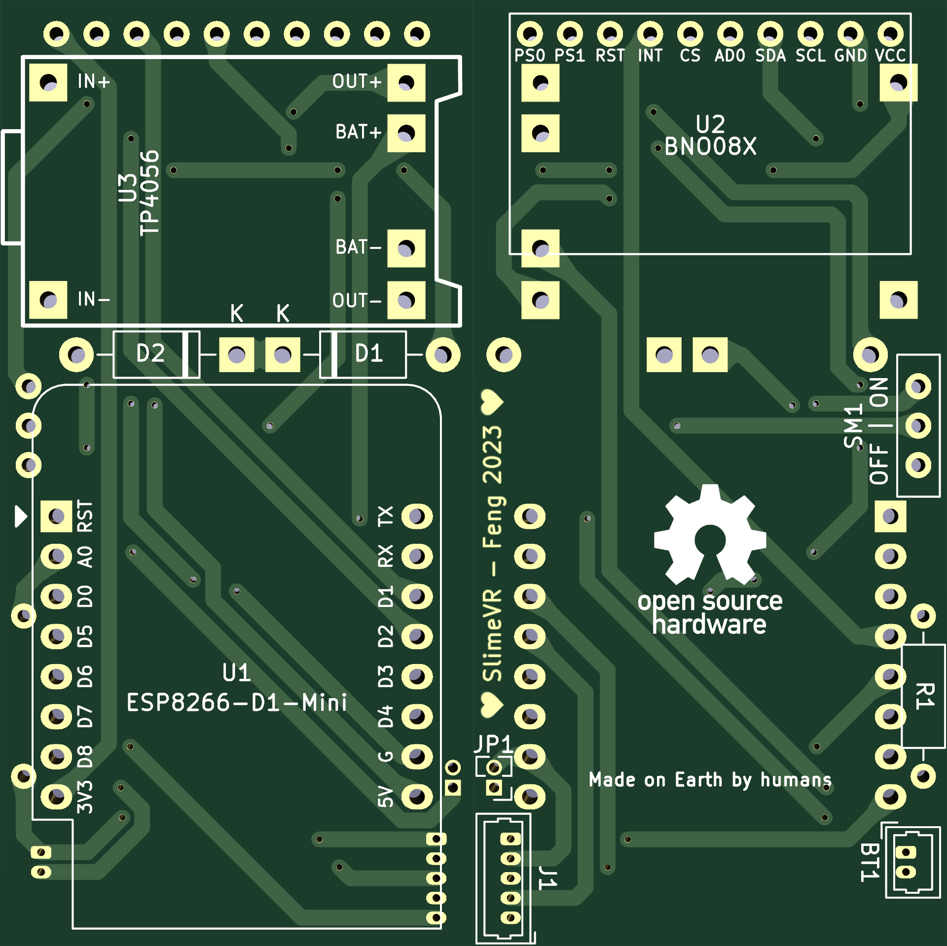
| Qty | Value | Footprint | References |
|---|---|---|---|
| 2 | 1N5817 | Diode_THT:D_DO-41_SOD81_P10.16mm_Horizontal | D1, D2 |
| 1 | 180k | Resistor_THT:R_Axial_DIN0207_L6.3mm_D2.5mm_P10.16mm_Horizontal | R1 |
| 1 | Auxiliary_Tracker_Connector | SlimeVR:Molex_PicoBlade_53047-0510_1x05_P1.25mm_Vertical | J1 |
| 1 | BNO08X | SlimeVR:BNO08X | U2 |
| 1 | Battery_Cell | Connector_Molex:Molex_PicoBlade_53047-0210_1x02_P1.25mm_Vertical | BT1 |
| 1 | ESP8266-D1-Mini | SlimeVR:WEMOS_D1_mini_light | U1 |
| 1 | Jumper_2_Open | Connector_PinHeader_1.27mm:PinHeader_1x02_P1.27mm_Vertical | JP1 |
| 1 | MSK-12D19-1P2T | SlimeVR:MSK-12D19-1P2T | SM1 |
| 1 | TP4056 | SlimeVR:TP4056_MAO | U3 |

thiagoeustakio/bioin_tacto
This repository include all design files and source code for the sensing module describe in "BioIn-Tacto: A compliant multi-modal tactile sensing module for robotic tasks".


JGAguado/Smart_Plant
The Smart Plant is a board that can be plugged directly on the soil, close to the plant, that allows the measurement of the environment (soil moisture, environment temperature & illuminance), and presents the…
It measures 30 × 60 mm and has 2 copper layers, 1.6 mm thick.
10 parts, built around the BNO08X and TP4056. The full list of its parts is on this page, with links to each part's symbol and footprint where PCBKit's library has them.
From the R-Josef/SlimeVR-Hardware repository on GitHub, at the commit this page was made from: the board is SlimeVR-PCB/SlimeVR.kicad_pcb and its schematic SlimeVR-PCB/SlimeVR.kicad_sch. PCBKit opens the board in the browser, with nothing to install.
Its repository states no licence, so its author keeps all rights: ask R-Josef before reusing the design.