
2 layers79 × 30 mm
LIA
JGAguado/LIA
Low-power pet tracking platform built around Meshtastic and LoRa mesh networking
81 parts29

 JGAguado/Smart_Plant303
The Smart Plant is a board that can be plugged directly on the soil, close to the plant, that allows the measurement of the environment (soil moisture, environment temperature & illuminance), and presents the information on an ePaper display.
Smart Plant is an open-source printed circuit board by JGAguado, from the JGAguado/Smart_Plant repository on GitHub. It is a 2-layer board of 80 × 129.1 mm with 75 parts on 53 nets, routed with 575 tracks and 116 vias.
It is built around the ESP32-S2-MINI-1-N4R2, AHT20 and VEML7700-TR, with the MAX17048G+T10, RT9080-33GJ5 and TP4056 among its other parts. Its parts include 25 capacitors, 21 resistors, 8 diodes, 7 ICs and 3 connectors. It belongs with the lEDs and displays and sensors and measurement boards and the ESP32 boards of this library.


See how your plant is doing — on its own e-paper label and in Home Assistant.
Smart Plant measures soil moisture, light, temperature and humidity. Place it in your plant pot, read the measurements on the 2.9-inch e-paper display, and connect it to Home Assistant with ESPHome.
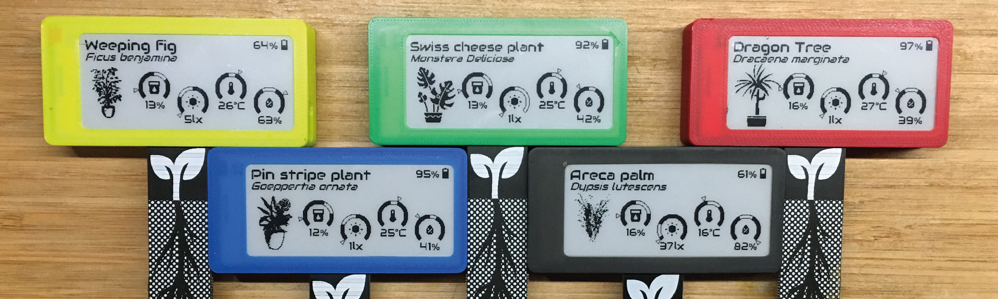
Get started · Create your plant label · Get a board · Read the documentation

The standalone configuration is the starting point for a single device. Read the safety instructions before assembly and flashing.
The companion Label-maker generates printable plant labels and e-paper backgrounds from JSON or YAML templates. Use it to add a plant name and illustration to your display.
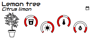
Follow the step-by-step label guide. Start with the plant examples and generator, then follow the programming guide to use the resulting background image. The firmware draws the live readings over that image.
| Setup | Starting point | During deep sleep |
|---|---|---|
| One device with the native ESPHome API | Standalone configuration | No network response; entity availability depends on Home Assistant setup. |
| Several devices with retained MQTT readings | MQTT example | Last published readings remain available. |
| Shared packages with the native ESPHome API | API example | No network response; entity availability depends on Home Assistant setup. |
The multi-device guide explains the shared hardware core and transport profiles. Each device sets its identity and credentials. Calibration and label images use shared defaults unless overridden.
Smart Plant combines an ESP32-S2, a soil-moisture probe, environmental sensors and an e-paper display. The repository includes board design files and printable enclosure models.
Use Discussions for questions and ideas. Report reproducible problems in Issues.
Contributions to firmware, documentation and examples are welcome. Describe the problem, the change and how you verified it in your pull request.
Created by J. G. Aguado, with contributions from the community.
This project uses CC BY-NC-SA 4.0. See the license for attribution, non-commercial use and sharing requirements.
| Qty | Value | Footprint | References |
|---|---|---|---|
| 10 | 1uF | C0603 | C7, C9, C13, C14, C17, C18, C19, C25, C27, C28 |
| 6 | 10uF | C0603 | C1, C4, C8, C10, C16, C20 |
| 5 | 10k | R0603 | R1, R7, R10, R15, R16 |
| 5 | SS14 | SMA-DIODE | D1, D2, D3, D5, D6 |
| 4 | 1M | R0603 | R8, R14, R18, R20 |
| 3 | 0.1uF | C0603 | C12, C15, C40 |
| 2 | 100nF | C0603 | C6, C11 |
| 2 | 1k | R0603 | R6, R11 |
| 2 | 4.7uF | C0603 | C2, C26 |
| 2 | 5.1k | R0603 | R36, R37 |
| 2 | LOGO | LOGO | G***, G*** |
| 2 | TPB1,27 | B1,27 | TP1, TP2 |
| 1 | 1X04 | J5 | |
| 1 | JST-2-SMD | J1 | |
| 1 | 0.47 | R0603 | R13 |
| 1 | 0.47nF | C0603 | C3 |
| 1 | 1.2k | R0603 | R4 |
| 1 | 1.5k | R0603 | R3 |
| 1 | 10K | R0603 | R9 |
| 1 | 10nF | C0603 | C5 |
| 1 | 10uH | INDUCTOR_4X4MM_NR401 | L3 |
| 1 | 1K | R0603 | R5 |
| 1 | 220 | R0603 | R17 |
| 1 | 240k | R0603 | R21 |
| 1 | 330R | R0603 | R2 |
| 1 | AHT20 | AHT20 | IC3 |
| 1 | E-PAPER-FPC | FPC_24_0.5MM | FPC0 |
| 1 | ESP32-S2-MINI-1-N4R2 | ESP32S2MINI1N4R2 | IC5 |
| 1 | Flash | TACTILE_SWITCH_SMD_5.2MM | S1 |
| 1 | Green | LED_0603 | LED2 |
| 1 | IRLML0100 | SOT23-3 | Q1 |
| 1 | LBSS84LT1G | SOT23 | T2 |
| 1 | LL4148 | LL-34 | D4 |
| 1 | MAX17048G+T10 | SON50P200X200X80-9N | IC7 |
| 1 | MMBT2222A | SOT23 | T1 |
| 1 | RT9080-33GJ5 | SOT94P280X100-5N | IC4 |
| 1 | Red | LED_0603 | LED1 |
| 1 | Reset | TACTILE_SWITCH_SMD_5.2MM | S2 |
| 1 | TLC555CDR | SO08 | IC2 |
| 1 | TP4056 | SOT23-8 | IC1 |
| 1 | USB-C | USB-C-16P-4LAYER-ISOLATED | J6 |
| 1 | VEML7700-TR | VEML7700-TR | IC6 |
JGAguado/LIA
Low-power pet tracking platform built around Meshtastic and LoRa mesh networking

pierrejay/10base-t1l-usb-adapter
Single Pair Ethernet 10BASE-T1L USB adapter (LAN9500A + DP83TD510E)

dan-stefanov/locatof-hw
Open-source localization project based on UWB Time-of-Flight ranging

DepartmentOfAlchemy/minimain-esp32-s2
PCB files for the MiniMain ESP32-S2 in an Adafruit Feather compatible format.

TH4R4V3N1324/hexapod-controller
Embedded firmware and hardware-support code for a hexapod robot controller. The repository contains firmware for the handheld/controller interface, an ESP32 wireless receiver, ATtiny1616 left and right boards, and a…

TH4R4V3N1324/Hexapod
This repository contains the complete design, control software and documentation for a six-legged walking robot (hexapod).

Alfaa123/Arduino-Thermostat
This is a project to create a Arduino powered home thermostat. Version 1 PCB schematic and design is complete.

gpgreen/eink-breakout
Kicad project for a Dalian Good Display Epaper breakout board for prototyping
It measures 80 × 129.1 mm and has 2 copper layers, 1.6 mm thick.
75 parts, built around the ESP32-S2-MINI-1-N4R2, AHT20, VEML7700-TR and MAX17048G+T10. The full list of its parts is on this page, with links to each part's symbol and footprint where PCBKit's library has them.
From the JGAguado/Smart_Plant repository on GitHub, at the commit this page was made from: the board is Design/Smart_Plant.kicad_pcb and its schematic Design/Smart_Plant.kicad_sch. PCBKit opens the board in the browser, with nothing to install.
Its repository states no licence, so its author keeps all rights: ask JGAguado before reusing the design.