2 layers165 × 85 mm
Sprinkler System
Swamp-Ig/Sprinkler-System
PCB design for five zone sprinkler system. For ESPHome with an Esp32 module.
80 parts

 uttkarsh-chimane/Isolated-AC-DC-SMPS-Based-Power-Module1
An isolated 230VAC to 5VDC power supply using the HLK-PM01 AC-DC module with input protection, EMI filtering, and custom PCB design in KiCad 10.
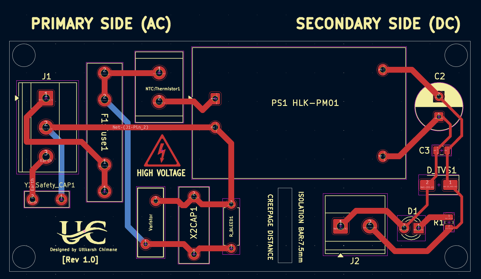
Isolated SMPS Based Power Module is an open-source printed circuit board by uttkarsh-chimane, from the uttkarsh-chimane/Isolated-AC-DC-SMPS-Based-Power-Module repository on GitHub, published under the MIT licence. It is a 2-layer board of 80 × 40 mm with 16 parts on 8 nets, routed with 65 tracks and 0 vias.
It is built around the HLK-PM01, 10D471K and 470UF 10V 6.3*7, with the SMBJ5.0A among its other parts. Its parts include 2 capacitors, 2 connectors, 2 crystals, 1 resistor and 1 diode. It belongs with the power boards of this library.


Overview • Features • Hardware Architecture • Schematic Highlights • PCB Insights • Specifications





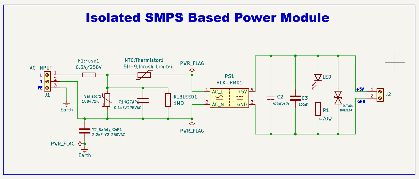
A compact, isolated AC-to-DC Switch Mode Power Supply (SMPS) built around the HLK-PM01 module. The design incorporates comprehensive mains input protection, EMI suppression, primary-secondary galvanic isolation, and a regulated 5V DC output, making it suitable for embedded systems, IoT devices, and industrial electronics.
This project presents the design of an isolated 230VAC to 5VDC power supply using the HLK-PM01 AC-DC converter module. The objective was to develop a compact, safe, and reliable power supply suitable for powering embedded systems, microcontrollers, and IoT devices.
The design integrates the essential protection and filtering stages required for a mains-powered supply, including:
🧩 3D PCB Render
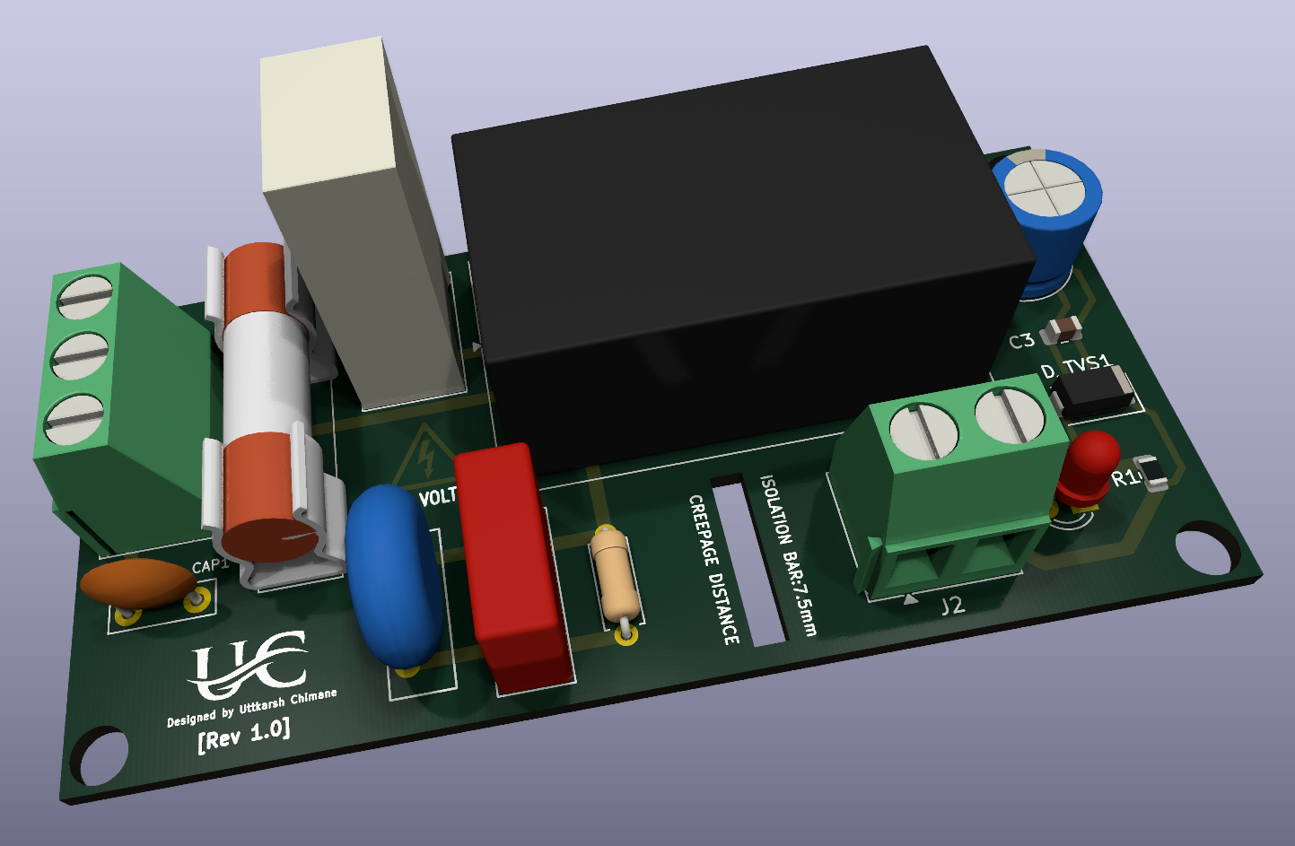
🔌 PCB Layout
⚙️ Schematic
230VAC Input
      │
      ▼
 Fuse Protection
      │
      ▼
NTC Thermistor
      │
      ▼
 MOV + X2 Capacitor
      │
      ▼
 HLK-PM01
(Isolated AC-DC Module)
      │
      ▼
Output Filter
(470µF + 100nF)
      │
      ▼
 TVS Protection
      │
      ▼
LED IndicatorInput protection
EMI suppression
Power conversion
Output stage
| Parameter | Value |
|---|---|
| Project | Isolated 230VAC to 5VDC Power Supply using HLK-PM01 |
| Input Voltage | 230 VAC, 50 Hz |
| Output Voltage | 5 V DC |
| Output Power | 3 W |
| Output Current | Up to 600 mA |
| AC-DC Module | Hi-Link HLK-PM01 |
| Input Protection | 0.5 A Fuse, MOV (10D471K), 5D-9 NTC |
| EMI Filter | X2 Capacitor, Y2 Capacitor, 1 MΩ Bleeder |
| Output Protection | SMBJ5.0A TVS Diode |
| Output Filter | 470 µF + 100 nF Capacitors |
| Isolation | Galvanically Isolated (basic, 7.5 mm barrier) |
| PCB | Single-Layer FR-4 |
| Design Software | KiCad 10 |
| ERC Status | ✅ Passed (0 Errors) |
| DRC Status | ✅ Passed (0 Errors) |
| Applications | ESP32, Arduino, IoT, Embedded Systems |
| Qty | Value | Footprint | References |
|---|---|---|---|
| 1 | 0.1uF/275VAC | Capacitor_THT:C_Rect_L13.0mm_W5.0mm_P10.00mm_FKS3_FKP3_MKS4 | X2CAP1 |
| 1 | 0.5A/250V | Fuse:Fuseholder_Littelfuse_100_series_5x20mm | F1:Fuse1 |
| 1 | 100nF | Capacitor_SMD:C_0805_2012Metric | C3 |
| 1 | 10D471K | Varistor:RV_Disc_D12mm_W4.5mm_P7.5mm | Varistor |
| 1 | 1MΩ | Resistor_THT:R_Axial_DIN0207_L6.3mm_D2.5mm_P7.62mm_Horizontal | R_BLEED1 |
| 1 | 2.2nF Y2 250VAC | Capacitor_THT:C_Disc_D7.5mm_W2.5mm_P5.00mm | Y2_Safety_CAP1 |
| 1 | 470uF/10V | Capacitor_THT:CP_Radial_D8.0mm_P3.50mm | C2 |
| 1 | 470Ω | Resistor_SMD:R_0805_2012Metric | R1 |
| 1 | 5D-9,Inrush Limiter | Resistor_THT:R_Radial_Power_L12.0mm_W8.0mm_P5.00mm | NTC:Thermistor1 |
| 1 | AC INPUT | TerminalBlock_Phoenix:TerminalBlock_Phoenix_MKDS-1,5-3-5.08_1x03_P5.08mm_Horizontal | J1 |
| 1 | HLK-PM01 | Converter_ACDC:Converter_ACDC_Hi-Link_HLK-PMxx | PS1 HLK-PM01 |
| 1 | LED | LED_THT:LED_D3.0mm | D1 |
| 1 | LOGO | LOGOs:UC 15x15mm | G*** |
| 1 | SMBJ5.0A | Diode_SMD:D_SMA | D_TVS1 |
| 1 | Screw_Terminal_01x02 | TerminalBlock_Phoenix:TerminalBlock_Phoenix_MKDS-1,5-2-5.08_1x02_P5.08mm_Horizontal | J2 |
The 15 most common of 16 parts.
Swamp-Ig/Sprinkler-System
PCB design for five zone sprinkler system. For ESPHome with an Esp32 module.


jrtaylor71/ESP32-DevKitC3-Simple-Thermostat-PCB
ESP32-DevKitC3 Simple Thermostat with PCB

jrtaylor71/ESP32-Simple-Thermostat
Simple ESP32 Thermostat with touch screen


doug7410/nowplaying-appliance
Build guide, BOM and hardware for the Now-Playing desk appliance: HUB75 spectrum + touch now-playing display driven by room-mic song recognition

jamesburton/Lolin32OLEDLaserTagTest
Reverse-engineering, decoding, and transmitting Vatos infrared laser-tag signals across two ESP32 boards:
It measures 80 × 40 mm and has 2 copper layers, 1.6 mm thick.
16 parts, built around the HLK-PM01, 10D471K, 470UF 10V 6.3*7 and SMBJ5.0A. The full list of its parts is on this page, with links to each part's symbol and footprint where PCBKit's library has them.
From the uttkarsh-chimane/Isolated-AC-DC-SMPS-Based-Power-Module repository on GitHub, at the commit this page was made from: the board is hardware/Isolated SMPS Based Power Module.kicad_pcb and its schematic hardware/Isolated SMPS Based Power Module.kicad_sch. PCBKit opens the board in the browser, with nothing to install.
Its repository publishes it under the MIT licence: you may reuse it on that licence's terms (keep the author's notice, and for a copyleft licence share your changes alike).