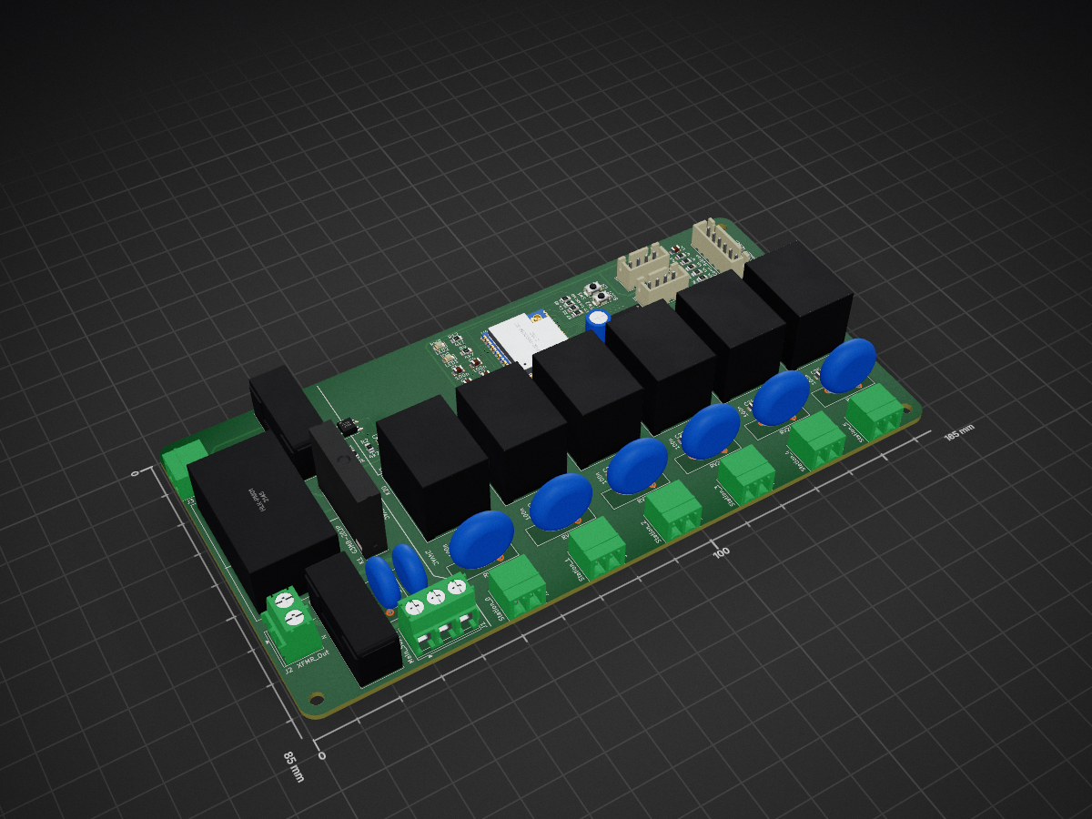
Sprinkler System is an open-source printed circuit board by Swamp-Ig, from the Swamp-Ig/Sprinkler-System repository on GitHub. It is a 2-layer board of 165 × 85 mm with 80 parts on 78 nets, routed with 511 tracks and 36 vias.
It is built around the ESP32-WROOM-32U, HLK-PM01 and AMS1117-3.3, with the EL817, ULN2803A and 10D471K among its other parts. Its parts include 20 resistors, 13 capacitors, 12 connectors, 9 switches and 5 ICs. It belongs with the home automation and IoT boards and the ESP32 boards of this library.
A custom PCB for controlling up to six 24 VAC irrigation solenoid valves via WiFi, using an ESP32 and ESPHome with native Home Assistant integration.
Features
6 independent zones — each zone switches a 24 VAC solenoid valve via an Omron G5LE-1 relay
WiFi control — ESP32-WROOM-32U with external U.FL antenna connector
Home Assistant integration — ESPHome firmware; zones appear as switch entities
Onboard power supply — HLK-PM01 AC-DC module (mains → 5 V); AMS1117-3.3 regulator (5 V → 3.3 V for ESP32)
Relay isolation — ULN2803A Darlington array isolates ESP32 GPIOs from relay coil drive current
Protected design — varistors on each zone output and across the mains input and transformer primary (RV1/RV2), time-delay fuses on the mains and 24 VAC supplies, per-zone RC snubbers, and an optocoupler-isolated 24 VAC rail sense
⚠️ Safety
This board carries mains voltage (Line and Neutral) on the PCB.
The HLK-PM01 module is connected directly to mains. The 24 VAC solenoid rail is transformer-isolated but still carries AC voltage.
Do not touch or probe the board while it is powered.
The enclosure must be non-conductive and fully closed before applying mains power.
All mains wiring must comply with local electrical codes. Use appropriately rated cable and terminals.
The external transformer must be safety-rated (UL, CE, or equivalent) for your locale.
Replace fuses only with the specified ratings — see the BOM below.
See Assembly Notes for enclosure requirements and conformal coating instructions.
How It Works
The controller has three linked paths: logic power, 24 VAC valve power, and relay control.
Logic power: Mains → F1 → HLK-PM01 → 5 V → AMS1117-3.3 → 3.3 V → ESP32 + logic
24 VAC path: Mains → F1 → G3MB-202P SSR (K1, GPIO16) → J2 → external transformer → J3 → F2 → zone relays (K20–K25) → solenoids
When a zone is activated, the ESP32 first enables the 24 VAC rail (K1), then drives the selected relay through the ULN2803A. The ULN2803A acts as a low-side driver, keeping ESP32 GPIO current low while switching the 24 VAC solenoid load through the relay contacts.
Bill of Materials
Ref
Component
Value / Part No.
Notes
U4
ESP32 module
ESP32-WROOM-32U
External antenna (U.FL)
U3
AC-DC module
HLK-PM01
100–240 VAC in, 5 V / 600 mA out
U1
LDO regulator
AMS1117-3.3
SOT-223
U2
Optocoupler
EL817
Isolates the 24 VAC rail sense
U5
Darlington array
ULN2803A
SOIC-18
K1
Solid-state relay
Omron G3MB-202P
Gates the 24 VAC solenoid rail (GPIO16)
K20–K25
Relay ×6
Omron G5LE-1
SPDT, 5 V coil, 10 A / 250 VAC contacts
RV20–RV25
Varistor ×6
68 V
Surge protection, one per zone output
RV1
Varistor
10D471K (275 VAC)
Across mains L–N input, after F1
RV2
Varistor
10D471K (275 VAC)
Across K1 SSR output / transformer primary
F1
Fuse
T1A (time-delay)
Mains supply — slow-blow for transformer/HLK inrush
F2
Fuse
T2A (time-delay)
24 VAC supply — slow-blow for solenoid inrush
D1
Diode
1N4148 (0805)
24 VAC rail sense
C5
Capacitor
220 µF / ≥10 V
5 V rail bulk reservoir (THT radial)
C1, C7
SMD capacitors
10 µF
Supply filtering
C2, C3
SMD capacitors
22 µF
Supply filtering / sense
C4, C6, C20–C25
SMD capacitors
100 nF
ESP32 VDD (C4), EN reset (C6), zone snubbers (C20–C25)
Wiring & GPIO — connector pinouts and GPIO assignments
ESPHome Configuration — full firmware config, fault detection, and optional pump relay setup
Assembly Notes — step-by-step build and commissioning guide
Project Structure
text
Sprinkler System.kicad_pro    ← KiCad project file
Sprinkler System.kicad_sch    ← Schematic
Sprinkler System.kicad_pcb    ← PCB layout
Sprinkler System.pretty/      ← Custom footprints and 3D models
symbols/                       ← Custom symbol library (G3MB-202P)
manufacturing/
  gerbers/                     ← Gerber files for PCB fabrication
  drill/                       ← Excellon drill files
  pos/                         ← Pick-and-place centroid files
  bom/bom.csv                  ← Bill of materials
docs/
  schematic.pdf                ← Schematic PDF
  pcb.pdf                      ← PCB layer PDF
  board.step                   ← 3D STEP model
  wiring.md                    ← Connector and GPIO reference
  esphome.md                   ← ESPHome firmware configuration
  assembly.md                  ← Build and commissioning guide
.githooks/pre-commit           ← Auto-exports fabrication outputs on commit
setup / setup.ps1              ← One-time dev environment setup
release / release.ps1          ← Tag a release version
Developing
First-time setup
powershell
.\setup.ps1
Configures the git hook path and verifies kicad-cli is available. Use ./setup in Git Bash / WSL.
Fabrication exports
Gerbers, drill files, PDFs, BOM, netlist, and STEP are regenerated automatically by the pre-commit hook whenever Sprinkler System.kicad_pcb or Sprinkler System.kicad_sch are staged. No manual export step is needed.
Run DRC and ERC from within KiCad before committing — fix all errors before submitting to a board house.
Releasing
powershell
.\release.ps1 v1.1.0
Stamps the schematic and PCB title blocks with the version and date, commits (triggering a fresh fabrication export), and creates the git tag. Use ./release v1.1.0 in Git Bash / WSL. Then push:
It measures 165 × 85 mm and has 2 copper layers, 1.6 mm thick.
What parts does the Sprinkler System use?
80 parts, built around the ESP32-WROOM-32U, HLK-PM01, AMS1117-3.3 and EL817. The full list of its parts is on this page, with links to each part's symbol and footprint where PCBKit's library has them.
Where can I download the Sprinkler System KiCad files?
From the Swamp-Ig/Sprinkler-System repository on GitHub, at the commit this page was made from: the board is Sprinkler System.kicad_pcb and its schematic Sprinkler System.kicad_sch. PCBKit opens the board in the browser, with nothing to install.
Can I use the Sprinkler System design in my own project?
Its repository states no licence, so its author keeps all rights: ask Swamp-Ig before reusing the design.