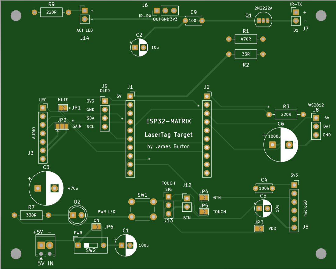
Layouts is an open-source printed circuit board by jamesburton, from the jamesburton/Lolin32OLEDLaserTagTest repository on GitHub. It is a 2-layer board of 100 × 80 mm with 38 parts on 32 nets, routed with 247 tracks and 9 vias.
It is built around the 100UF 10V 4*7, 2N2222A and 470UF 10V 6.3*7. Its parts include 12 connectors, 7 capacitors, 5 resistors, 2 switches and 1 diode.
Reverse-engineering, decoding, and transmitting Vatos infrared laser-tag
signals across two ESP32 boards:
Lolin32 OLED (ESP32 + 128×32 SSD1306) — IR monitor / decoder / transmitter
and the C# trainer feeder. Reads NEC remotes and Vatos shots to the OLED, and
fires Vatos shots via an IR LED.
ESP32-S3-Matrix (ESP32-S3 + 8×8 WS2812) — a wearable target: idles in
a rainbow, tracks its own health, flashes the firing team's colour and goes
briefly dark when hit, and holds dark when its health reaches zero.
Both boards support wireless OTA updates and UDP telemetry (see
Wireless). A network control plane (REST + UDP) configures and
controls devices, with a .NET client library on the host side (see
Control plane). Shared logic lives in libraries:
lib/Vatos (decode/encode), lib/IrFramer (IR edge framing), lib/TagNet
(WiFi + OTA + HTTP + UDP), and lib/ControlProto (the protocol-agnostic wire
codec for the control plane).
The Vatos IR protocol is not documented publicly; the protocol description in
docs/gun-protocol.md was reverse-engineered from scratch in this project.
Vatos laser-tag shots → team + damage (e.g. Blue 2)
Displays the decode on the on-board OLED, with a blink LED on every hit.
Transmits valid Vatos shots via an IR LED (38 kHz carrier, correct frame
checksum), triggered by the BOOT button or any byte over serial.
Trains/recognises signals from a PC via the C# IrSignalTrainer app,
matching NEC codes exactly and other protocols by full-frame fingerprint.
Networks the target: broadcasts discovery heartbeats and hit/state
telemetry over UDP, serves a JSON REST API for config/control, accepts
low-latency UDP control broadcasts, and is driven from a host-side .NET
client library (see Control plane).
Hardware
Carrier PCB (ESP32-S3-Matrix target)
A custom 100×80 mm 2-layer carrier board for the S3 target lives in
hardware/lasertag-carrier/: socketed
ESP32-S3-Matrix, MAX98357A audio, microSD, IR RX + transistor IR-TX driver,
WS2812 strip output, OLED header, GP2 role selector, power switch and M3
mounting holes.
Ordering from PCBWay? New users can use this referral link for $5 off
their first order: https://pcbway.com/g/2F9n3B
Lolin32 OLED (monitor / decoder / transmitter)
Function
Pin
Notes
OLED I²C
SDA = GPIO5, SCL = GPIO4
SSD1306, 128×32, address 0x3C
IR receiver (VS1838B)
OUT = GPIO25
demodulating; idles HIGH, pulses LOW
Activity LED
GPIO26
blinks ~80 ms on each received frame
IR transmit LED
GPIO13
38 kHz carrier via the LEDC peripheral
Test-shot trigger
GPIO0 (BOOT) or serial
any serial line also fires a shot
ESP32-S3-Matrix (target)
Function
Pin
Notes
8×8 WS2812 matrix
GPIO14
on-board, 64 LEDs (NeoPixel)
IR receiver (VS1838B)
OUT = GPIO1
GPIO10–14 are taken by the IMU/matrix
Activity LED
GPIO7
blinks on each received frame
(reserved)
GPIO10–13
on-board QMI8658 IMU
Behaviour: rainbow when idle → on a Vatos hit, subtract the shot's damage from
its health (max health 32), flash the firing team's colour (Blue/Red/Green/White)
4×, then go dark for a brief configurable "stunned" interval (default ~1–5 s;
tune via the control plane) → resume rainbow, keeping accumulated damage. The
4 central columns of the 8×8 matrix form a health bar: they deplete
top-down as health drops (outer 4 columns stay rainbow). At 0 health it
holds dark ("dead") until a respawn / reset. The device is authoritative for
its own health and emits EVT hit / EVT state telemetry as it changes (see
Control plane). Matrix current is capped to 500 mA
(setMaxPowerInVoltsAndMilliamps) for USB safety.
Notes:
The on-board OLED on this unit is a 128×32 SSD1306 (not the 128×64 the
Lolin32 normally ships with). Driving it as 128×64 renders garbled,
interlaced text — the src/display_test.cpp diagnostic cycles candidate
driver/geometry configs to identify the right one.
The OLED is not on the ESP32 default I²C pins, so Wire.begin(5, 4) is
required.
The receiver/transmit/indicator LEDs in this build are driven without series
resistors at the ESP32's minimum drive strength (GPIO_DRIVE_CAP_0, ~5 mA)
to protect the pins. This is fine for bench/loopback testing but limits IR
transmit range — a transistor driver + resistor is needed for real range.
Build, flash, monitor
PlatformIO project (Arduino framework; boards
lolin32 and esp32-s3-devkitc-1, plus a native env for unit tests).
sh
pio run -e lolin32 # build
pio run -e lolin32 -t upload --upload-port COM14 # flash
pio device monitor -p COM14 -b 115200# serial monitor
Environments:
lolin32 — Lolin32 firmware (src/main.cpp).
lolin32_displaytest — the OLED config finder (src/display_test.cpp).
pio run -e esp32-s3-matrix -t upload --upload-port COM7   # flash the Matrix
pio test -e native                                        # run ControlProto unit tests
Flashing workaround (Lolin32)
This particular board has no BOOT/EN buttons and its USB auto-reset into the
bootloader is unreliable, so uploads may fail with
Wrong boot mode detected (0x17). To flash:
Jumper GPIO0 → GND.
Run the upload — the chip now enters download mode and flashes.
Remove the GPIO0–GND jumper and reset (re-plug USB) so it boots normally.
If the board disappears from Windows entirely, unplug/replug the USB to
re-enumerate the CP210x serial port.
Wireless
Both firmware targets bring up WiFi, ArduinoOTA, and UDP telemetry via the
shared lib/TagNet library.
Set WiFi credentials (over serial)
Credentials are stored in NVS, set with serial commands (no rebuild):
or manually in a serial monitor: ssid <name>, pass <pw>, wifi-save
(also wifi-status, wifi-clear). The board prints its IP once connected.
Board-config overrides (cfg command)
A whitelisted subset of board-profile fields can be overridden at runtime
without a rebuild:
text
cfg <key> <value>
Examples: cfg matrixOrder 1, cfg matrixPin 27, cfg activityLedPin 26.
Changes are saved to NVS and applied on the next reboot.
OTA updates
After one USB flash + WiFi provisioning, update over the air — no cable, no
GPIO0 jumper.
For the S3 fleet, prefer the host's ota command (see
Game manager): every board now runs 2.1.0, which serves
POST /api/update, so ota all flashes the whole fleet over HTTP with no
Python and no per-board IP chasing. The espota route below is now only needed
to bootstrap a board running pre-2.1.0 firmware (it has no /api/update),
and for the Lolin32.
sh
pio run -e lolin32-ota -t upload          # -> lasertag-lolin32 (IP in platformio.ini)
pio run -e esp32-s3-matrix-ota -t upload  # -> lasertag-matrix  (IP in platformio.ini)
⚠ ota all sends one binary to every online outdated board and cannot
tell an ESP32 from an ESP32-S3 (heartbeats carry no chip field). With the
Lolin32 (ESP32) on the network alongside the S3 fleet, target it
explicitly with ota <id> rather than all.
Both *-ota envs target the boards' IP addresses in platformio.ini.
mDNS (lasertag-*.local) resolves fine for ping/REST on this dev machine, but
espota is unreliable with mDNS names, so OTA sticks to IPs — resolve the
current one with ping lasertag-matrix.local (the matrix roams via DHCP) and
update upload_port if it changed, or set a DHCP reservation. OTA can take
several minutes over a weak link (low RSSI), but is reliable.
Telemetry monitoring
Devices broadcast discovery heartbeats and hit/state telemetry as UDP lines on
port 4210 (see Control plane for the grammar). The
tools/TagMonitor console app prints them raw:
mode= in a heartbeat is the board's role (idle/target/scoreboard),
not the match phase — a board reads mode=idle throughout a running
match. There is no per-board match-phase readback; the host is authoritative.
Discovering boards: listen to the heartbeat roster (TagMonitor, the host's
devices, or either manager) and give it ~30 s. Don't port-scan the subnet
— it misses boards that answer slowly, and every board roams on DHCP, so any IP
written down here or in platformio.ini may already belong to something else.
No telemetry but REST works? That's a missing inbound firewall rule or
a lossy weak-RSSI link. Rule out the firewall with tools/setup-firewall.ps1
(Windows, self-elevating) / tools/setup-firewall.sh (Linux/macOS).
Control plane (V2)
A protocol- and mode-agnostic network layer for configuring, controlling, and
monitoring devices. REST (reliable, JSON) handles config/CRUD/status; UDP
(fast, fire-and-forget on port 4210) handles discovery, telemetry, and
low-latency broadcast control. Devices decode IR into a generic TagEvent
(behind an IrProtocol abstraction — Vatos is the first protocol) and teams are
a generic indexed set, so game modes and the host never hard-code Vatos.
The full design and the authoritative wire contract (with golden test vectors)
live in
docs/superpowers/specs/.
REST API (served by the device)
Method
Route
Purpose
GET
/api/status
live runtime status (mode, hp, team, online, fw, uptime, rssi)
partial update; persists to NVS; unknown field → 400
POST
/api/mode
set runtime activeMode + timings (not persisted)
POST
/api/command
one-shot actions: identify, bright, test hit, debug
Identity + preferences persist in NVS; game state (mode, timings, health) is
runtime only, so a reboot returns the device to a neutral idle. Write
requests must send Content-Type: application/json — the ESP32 WebServer
discards a urlencoded body (curl's default); the .NET client sets the header
automatically. (GET / and GET /cmd?c= remain as deprecated aliases.)
UDP line-protocol (port 4210)
One message per packet; device→broadcast lines are prefixed with the hostname.
EVT/HB come from the device; CTL is sent to devices. The device is
authoritative for its own health; the host tallies match state from the event
stream. Send CTL to the subnet broadcast (e.g. 192.168.1.255) — the
limited broadcast 255.255.255.255 is not delivered on this LAN.
.NET host library
dotnet/LaserTag.Client (net10.0) is the typed host client:
dotnet/openapi/lasertag.yaml describes the REST surface (for generating other
clients). dotnet/LaserTag.Smoke is a throwaway harness that exercises the
library against a live device; run it for a quick end-to-end check:
sh
dotnet test dotnet/LaserTag.sln # unit tests
dotnet run --project dotnet/LaserTag.Smoke -- 192.168.1.2420# live REST + UDP roster
Game manager (host)
dotnet/LaserTag.Host orchestrates matches over the control plane (spec:
docs/superpowers/specs/2026-07-12-game-manager-design.md):
sh
dotnet run --project dotnet/LaserTag.Host # auto-detects the subnet broadcast# devices | start dm 5m [--kill 5 --hit 1 --waves 30s] | start elim [--timer 10m]# start chase <dur|--first N> [--min d] [--max d] [--gap d] [--penalty N] [--dark]# score | stop | reset [id] | activate [id] | deactivate [id] | quit# team <id|all> <0-4|none> — assign a board's team (0/none = neutral target)# teams split <n> — deal the online roster round-robin into n sides# fs ls|put|get|rm|play|startup <id> … — manage sound clips in on-board flash# fw [bin] — fleet firmware table: running vs available (from the# LTFW: marker embedded in firmware.bin)# ota <id|all> [--force] — push firmware over HTTP to online boards; `all`# targets outdated boards only (--force re-pushes)
Fleet OTA (firmware ≥ 2.1.0): every board serves POST /api/update
(multipart firmware upload → verified flash → reboot) and a browser upload
form at GET /update, so updates work from the host CLI, a browser, or the
future phone app — no espota/python needed. Spec:
docs/superpowers/specs/2026-07-27-fleet-ota-design.md. Boards on older
firmware need one last espota flash to gain the endpoint.
Sound clips in on-board flash (firmware ≥ 2.4.0)
Clips live in the board's on-board flash, in the partition table's
otherwise-unused 1.375 MB data partition (LittleFS). No microSD, no socket, no
wiring. Manage them remotely:
sh
fs ls <id> [dir]# storage usage + directory listing
fs put <id> <local> <remote> # upload, e.g. fs put e45614 assets/sfx/startup-rise.wav /sfx/startup.wav
fs get <id> <remote> <local> # download
fs rm <id> <remote> # delete (files only; directories are refused)
fs play <id> <remote> # play a clip now
fs startup <id> <remote|none> # set/clear the power-on cue
REST equivalents on each board: GET /api/files?path=,
POST|GET|DELETE /api/files/file?path=, and
POST /api/command {"cmd":"play","path":"…"}.
Clips must be 16 kHz / 16-bit / mono WAV — the parser rejects anything else
rather than converting. Generate one with
python tools/gen_sfx.py --wav out.wav --clip startup|death, or convert any
source with
ffmpeg -i in.mp3 -ac 1 -ar 16000 -sample_fmt s16 out.wav.
There is no clip length limit. Playback streams from flash in chunks and
feeds the task watchdog, so clip size is bounded by the partition (~1.4 MB,
about four 10-second clips) rather than by free RAM. Both former limits are
gone: clips used to be capped at ~3 s by the watchdog, and at ~270 KB by having
to fit in the heap.
Startup sound defaults to none. Set it per board with fs startup; it is
stored as startupSfx and played once at the end of boot. An unset, missing
or malformed clip is skipped silently so a board always comes up.
Clips survive firmware updates — OTA replaces the app partition only.
A clip that no config field references is reachable only via the API, which
is how to keep a "secret" sound with no on-board trigger.
Every caller-supplied path is validated on the device: absolute, no ..
segment. That check is the only thing between a LAN request and the
filesystem, so it is unit-tested natively.
microSD is optional and currently unproven. The code remains (sdprobe,
sdpins, sdscan are useful hardware diagnostics), but no board here has ever
mounted a card — see the handoff for the electrical findings.
Teams (firmware ≥ 2.2.0)### Teams (firmware ≥ 2.2.0)
A device's team lives in its persisted config (ownTeam), not the control
plane: a match reads each board's team from its heartbeat and snapshots it when
the lobby forms. Assign teams from any surface:
sh
# Host CLI
team <id|all> <0-4|none> # one board, or the whole roster
teams split <n> # deal the online roster round-robin into n sides# Web / Android manager: the team buttons on each Devices card# JSON API
curl -X POST http://<host>:5080/api/team -H 'content-type: application/json' \
-d '{"id":"752b38","team":1}'
Team 0 = none = a neutral target, and it is the default. A neutral board
is shootable by everyone, hits on it score for the shooter's team, and it can
never win a match — the right default for a target that isn't playing for a
side. This matches what the firmware has always done physically: it has never
own-team filtered, so every decoded shot damages the board that receives it.
Boards provisioned before 2.2.0 keep whatever team they were given (most were
2); team all none resets them.
teams split uses a stable order (by device id), so the same fleet always
splits the same way rather than reshuffling sides between matches.
⚠ Teams take effect from the next match. The lobby fixes each
participant's team at start, so reassigning mid-round does not move a player —
that would silently rewrite who the existing scores belonged to.
⚠ The lobby is fixed at match start. Devices that come online after the
countdown are ignored for the rest of the match (a device that drops and
returns does rejoin, and gets a re-issued CTL start id=).
Match rules live in dotnet/LaserTag.Game (IGameMode: Deathmatch,
Elimination, Chase — see docs/superpowers/specs/2026-07-27-chase-mode-design.md).
Scoring is per-team — the IR protocol carries the shooter's team, not a
player id. CTL grammar v2 (countdown, gameover, activate/deactivate,
optional id= addressing) is emitted by the host today.
Boards double as scoreboards during any match — the host pushes CTL Score
updates on change plus a 1 s live refresh, so a board's own OLED/matrix shows
the running score without extra wiring. A board can also run standalone as a
dedicated scoreboard outside of a match via POST /api/mode {"mode": "scoreboard"}.
Firmware compatibility: firmware at or above this build enforces id=
addressing, so an id=-addressed reset/start/activate/deactivate
only reaches the targeted device. Boards still running older firmware ignore
the id= filter and apply addressed CTLs to every device on the arena —
reflash all boards to the current firmware before running a multi-device
match.
Managers: web and Android
Two graphical front ends for running a game, alongside the console REPL. Both
render the same screens from the same code and run the same match engine —
they differ only in which machine the engine runs on.
text
        LaserTag.Ui (Blazor screens + IGameSession)
                    /                \
      LaserTag.Web                    LaserTag.App
   engine on the PC                engine on the phone
                    \                /
              LaserTag.Runtime (GameService, UDP listener, 4 Hz tick)
                    LaserTag.Game + LaserTag.Client
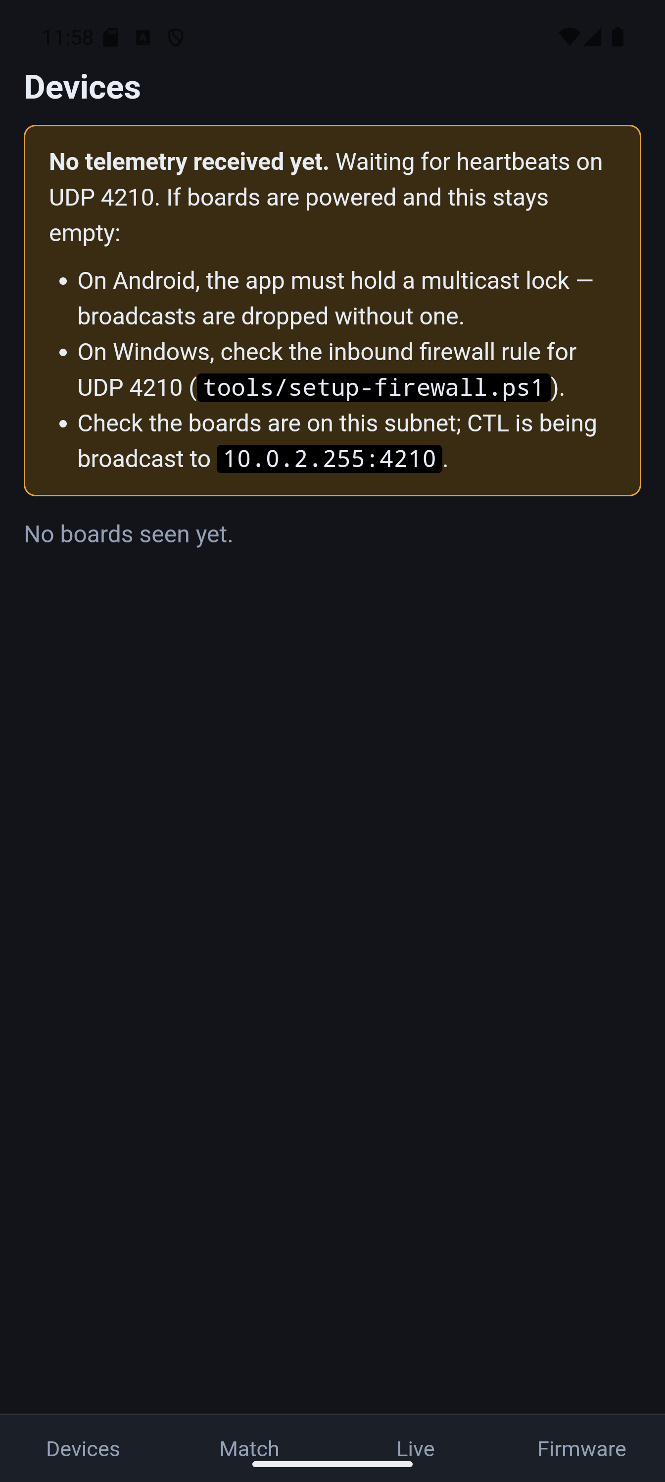
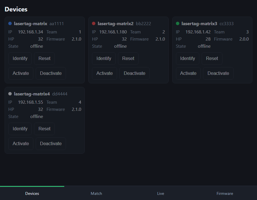
Screens: Devices (roster with identify/reset/activate per board), Match
(mode picker with per-mode parameters, start/stop), Live (scoreboard, player
table, event feed), Firmware (running-vs-available versions and one-tap OTA,
reusing the fleet-OTA pipeline).
Web manager
sh
dotnet run --project dotnet/LaserTag.Web            # http://<pc-ip>:5080
dotnet run --project dotnet/LaserTag.Web -- --broadcast 192.168.1.255
Binds 0.0.0.0:5080 over plain HTTP so any phone or laptop on the LAN can open
it — no install, and iPhone guests work too. A PC must be running at play time.
A JSON API sits alongside the UI for scripting:
Endpoint
Purpose
GET /api/devices
Roster with team, hp, firmware, online
GET /api/match
Phase, clock, scores, players
POST /api/match/start
Body e.g. {"mode":"chase","duration":"2m","firstTo":5}
The phone binds UDP 4210, runs the engine and broadcasts CTL itself, so no PC
is needed at play time — the point of the exercise. Requires the
maui-android workload (dotnet workload install maui-android).
Two Android-specific traps are handled in code, both of which produce a
silently-empty roster rather than an error:
Multicast lock. Android drops inbound broadcast UDP unless the app holds a
WifiManager.MulticastLock. AndroidMulticastGuard holds one for the
listener's lifetime; the manifest needs CHANGE_WIFI_MULTICAST_STATE.
MAUI never starts hosted services. Unlike the Generic Host, MauiApp
builds a service provider but does not run IHostedService, so the listener
and tick loop are started explicitly in App.OnStart.
Android app
Web manager
Status: the Android app runs — installed and driven on an Android 15
emulator, where the shared screens render, navigation works and broadcast
discovery picked up the right subnet. What is still unverified is the one
thing that matters most: receiving real telemetry. An emulator sits behind
NAT, so host broadcasts never reach it, and the multicast lock therefore could
not be exercised. Treat the first run on a real phone, on the same Wi-Fi as
the boards, as the true test.
Board capability HAL
Each board is described by a compile-time BoardProfile struct (selected with
-D BOARD_LOLIN32 or -D BOARD_S3_MATRIX in platformio.ini) that declares
its capabilities: IR rx/tx pins, hit-display type (WS2812 matrix, 3-pin RGB, or
none), OLED geometry, audio output (piezo or I2S DAC stub), and NVS storage.
Firmware and game-mode code target the HAL — HitDisplay, IrTx, Sound —
rather than raw pins, so the same game logic runs on any profiled board.
A whitelisted subset of profile fields (e.g. matrix data pin, pixel order,
activity LED pin) can be overridden at runtime via the cfg <key> <value>
serial command (see Board-config overrides);
overrides are persisted in NVS and applied at boot.
How it works
Receive path
An interrupt on the receiver pin timestamps every edge. Edges are grouped into
frames separated by ≥ 50 ms of silence (chosen so the gun's full-auto bursts
stay within one frame). Each completed frame is:
attempted as NEC (leader + 32 bits, validated by the command/inverse
byte) → emits NEC addr=0x.... cmd=0x..;
otherwise, if it is 41 edges, attempted as Vatos → emits
VATOS team=N(name) dmg=N;
always emitted raw as FRAME n=.. data=L..,H..,... for fingerprinting.
The optional decoded line is printed before the FRAME line so a consumer
can attach it to the frame that terminates the event.
Verified board-to-board (2026-07-29): an IR-TX-equipped board firing at
another decodes exactly — all four damage values cost exactly their damage,
and all four shooter teams arrive correctly in EVT hit shooterTeam=.
Two things to know when testing: range is very short on a raw GPIO drive
(aim the boards at each other, close), and shots arriving during the
post-hit flash/stun window are ignored by design (applyHit runs only in
the rainbow idle state), so space test shots ~4 s apart — a rapid burst
looks like a fault but isn't.
Transmit path
Vatos::encode() builds the 41-symbol bit pattern for a {team, damage} shot
(including the correct checksum). The firmware then gates a 38 kHz LEDC carrier:
even symbols are IR bursts (carrier on), odd symbols are gaps, each lasting
~380 µs (0) or ~800 µs (1). Pointing the IR LED at the VS1838B closes a full
loopback: transmitted shots are received and decoded by the same board.
Serial protocol (115 200 baud)
text
NEC addr=0x0707 cmd=0x04            # optional, precedes its FRAME
VATOS team=1(Blue) dmg=2           # optional, precedes its FRAME
FRAME n=75 data=L4520,H4490,...    # always; H/L = level held, value = µs
TX team=1(Blue) dmg=2              # printed when a shot is transmitted
The Vatos protocol (reverse-engineered)
A Vatos shot is a 41-edge frame on a ~38 kHz carrier: 21 IR bursts
interleaved with 20 gaps (it starts and ends with a burst). Every symbol is
short (~380 µs = 0) or long (~800 µs = 1); quantising at 600 µs gives a
stable 41-bit pattern.
The frame encodes the firing team and the shot's damage — not the
weapon:
It encodes damage, not weapon. Per the manual: Pistol = 1, Shotgun = 2,
SMG = 2, MG = 3, Rocket = 4. Because Shotgun and SMG both deal damage 2,
they transmit an identical frame — no receiver can tell them apart. So each
gun emits at most 4 distinct codes per team (4 teams × 4 damage = 16 total).
The audio is mislabelled on this unit: the spoken "Machine Gun" / "Sub
Machine Gun" names are swapped relative to the damage actually sent. Identify
shots by damage, not the voice line.
Carrier is ~38 kHz, confirmed because the (38 kHz) VS1838B demodulates the
gun cleanly. No 56 kHz receiver needed.
Both bursts and gaps carry payload. An early fingerprint that used only the
gap durations collided distinct shots (for some teams, damage 2 and damage 3
share gap patterns and differ only in the bursts). The working approach
fingerprints/decodes the full frame.
The full derivation, the 16-code matrix, and the bit map are in
docs/gun-protocol.md.
The Vatos library
lib/Vatos/ is a platform-independent decoder/encoder (no Arduino
dependencies — carrier generation lives in the caller):
decode() quantises 41 edge durations, validates the constant framing and
the checksum, and extracts team + damage.
encode() produces the 41-symbol pattern (even indices = bursts) for
transmission, with the correct checksum from a 4×4 lookup table.
Both directions were verified by full TX → IR → RX → decode loopback across
multiple team/damage codes, and decode() was verified against real gun fire.
RF (2.4 GHz) probe — CLOSED, no signal found
A side investigation into whether the Vatos kit also uses a 2.4 GHz link
alongside its IR. Result: nothing was detected, and the leading explanation
is that these gun-only units have no radio — see
docs/rf-protocol.md for the evidence and the retractions.
The tooling works and is kept for if the question reopens. An nRF24L01+ wired to
an ESP8266 (pio run -e esp8266-rfprobe) provides five serial commands:
Command
Purpose
selftest
Reads back written registers — proves the SPI wiring
scan [sweeps]
Fast sweep of all 126 channels via the power detector
watch from= to= ms=
Dwells per channel; far more sensitive to short bursts
dwell ch= secs=
Camps on one channel, 100 ms buckets for event correlation
sniff ch= rate= secs=
Promiscuous capture (2-byte address, CRC off)
Wiring: CE=GPIO4, CSN=GPIO5, SCK=GPIO14, MOSI=GPIO13, MISO=GPIO12, 3V3 with a
10 µF cap at the module. Captured RF … lines are analysed by the
LaserTag.Rf library (CRC16 validation, bit realignment, address recovery);
only a CRC-valid packet counts as a detection. Occupancy figures never do — that
lesson cost an evening and is written up in the findings doc.
The C# signal trainer
tools/IrSignalTrainer/ is a .NET console app that reads the board's serial
output and tags signals against named devices and buttons (see
tools/README.md).
sh
dotnet run --project tools/IrSignalTrainer # COM14, signatures.json
NEC signals match exactly on the decoded address:command code.
Other signals (e.g. the gun, before firmware decoding existed) match on a
quantised full-frame bit signature.
t trains (device + button, 4 samples), l lists, q quits. The library is
persisted to signatures.json.
signatures.json in the repo contains an example library trained on a TV remote
(NEC) and the Vatos gun.
The journey (how we got here)
A condensed log of the build, because most of the value was in the process:
Board bring-up. Adapted the manufacturer OLED example to PlatformIO and
verified the display + serial. Discovered the panel is 128×32, not
128×64 — the cause of unreadable, interlaced text — using a config-finder
sketch.
Sensor selection. Started with a KEYES photodiode + LM393 comparator
board. It is not a demodulating receiver, so its output fragmented/merged and
needed constant potentiometer tuning. Swapped to a VS1838B, which
produced clean, decode-grade frames with no tuning. (See
docs/sensor-comparison.md.)
NEC decoding. Added an NEC decoder to the firmware (OLED shows
addr:cmd) and validated it against a TV remote (address 0x0707).
Cracking the gun. The gun was not NEC. Captured frames, decoded the
structure, and — crucially, with the owner's manual + the spotted audio/icon
mismatch — realised the IR encodes team + damage, which explained an
apparent "Shotgun = Machine Gun" collision (it is really Shotgun = SMG, both
damage 2). Captured the full 4-team × 4-damage matrix and isolated the team,
damage, and checksum bit-fields.
Library + transmit. Factored the decode/encode into lib/Vatos/, added a
38 kHz IR transmitter, and verified the whole chain by loopback.
Repository layout
text
platformio.ini            PlatformIO config (lolin32 / displaytest / matrix + OTA + native)
src/
  main.cpp                Lolin32: RX + NEC/Vatos decode, OLED, IR transmit
  matrix_main.cpp         ESP32-S3-Matrix: 8x8 LED target + V2 control plane
  display_test.cpp        OLED driver/geometry config finder (separate env)
lib/
  Vatos/                  Platform-independent Vatos decode/encode
  IrFramer/               Shared IR edge-framing (ISR + frame assembly)
  TagNet/                 Shared WiFi (serial creds) + OTA + UDP + HTTP server
  ControlProto/           Protocol-agnostic control-plane wire codec + TagEvent
  Board/                  Compile-time BoardProfile per board (pins, capabilities)
  HitDisplay/             WS2812 matrix / RGB hit-feedback output HAL
  IrTx/                   IR transmit HAL
  Sound/                  Sound cues (piezo; I2S DAC stub)
  BoardNvs/               NVS override load + cfg serial command
test/
  test_board/             Native unit tests for Board/BoardNvs
  test_controlproto/      Native (host-compiled) unit tests for ControlProto
dotnet/                   .NET 10 host ecosystem (LaserTag.sln)
  LaserTag.Client/        Typed REST + UDP client library (parser, roster, client)
  LaserTag.Client.Tests/  xUnit tests
  LaserTag.Smoke/         Throwaway live smoke harness
  openapi/lasertag.yaml   OpenAPI description of the REST surface
tools/
The V2 control plane (REST + UDP config/control/telemetry, device-side
health, the .NET client library) is in place. Next:
Firmware game-mode framework + "Team Colours" mode — pluggable modes on
top of the activeMode/timings plumbing already wired through the control
plane.
Host scoring & orchestration — tally match state from the EVT stream;
multi-device game start/stop via CTL broadcasts.
.NET CLI + Claude skill — a runnable CLI over LaserTag.Client (the
library exists; its CTL sender must target the subnet broadcast), wrapped as
a Claude skill.
Real transmit range — a transistor driver + series resistor on the IR LED
for gameplay distances rather than bench loopback.
Pin down the checksum formula — currently a verified 4×4 lookup; the exact
algorithm (symmetric in team+damage) is not yet derived.
DigiSlate+ is based on the DigiSlate and is inspired by the DIY timecode generator from mitkunz. The aim for the DigiSlate+ is not only to be able to read and display timecode, but also to generate it itself.
Build guide, BOM and hardware for the Now-Playing desk appliance: HUB75 spectrum + touch now-playing display driven by room-mic song recognition
31 parts1MIT
Questions
How big is the Layouts PCB?
It measures 100 × 80 mm and has 2 copper layers, 1.6 mm thick.
What parts does the Layouts use?
38 parts, built around the 100UF 10V 4*7, 2N2222A and 470UF 10V 6.3*7. The full list of its parts is on this page, with links to each part's symbol and footprint where PCBKit's library has them.
Where can I download the Layouts KiCad files?
From the jamesburton/Lolin32OLEDLaserTagTest repository on GitHub, at the commit this page was made from: the board is hardware/lasertag-carrier/layouts/default/default.kicad_pcb. PCBKit opens the board in the browser, with nothing to install.
Can I use the Layouts design in my own project?
Its repository states no licence, so its author keeps all rights: ask jamesburton before reusing the design.