2 layers162.6 × 97.3 mm
Memory subsystem
TSJR/logic-analyzer
TTL logic analyzer built from 74xx logic and LED dot matrix display
73 parts

 TSJR/logic-analyzer
TTL logic analyzer built from 74xx logic and LED dot matrix display
Logic Analyzer is an open-source printed circuit board by TSJR, from the TSJR/logic-analyzer repository on GitHub. It is a 2-layer board of 50.3 × 80.3 mm with 16 parts on 38 nets, routed with 152 tracks and 2 vias.
It is built around the ATTINY85-15M and 74HC165D. Its parts include 4 capacitors, 4 ICs, 3 connectors, 1 resistor and 1 switch. It belongs with the sensors and measurement and lEDs and displays boards and the AVR (ATmega, ATtiny) boards of this library.


Breadboard and PCB-based logic analyzer built from discrete 74xx TTL logic, SRAM, and multiplexed LED matrix displays.
This project aims to build a fully discrete logic analyzer without using a microcontroller. The analyzer captures digital bus states into SRAM and displays captured samples on multiplexed LED matrices.
Project is currently in a state of active prototyping.
*This repository also contains a closely related project using an MCU-based design with 24 channels.
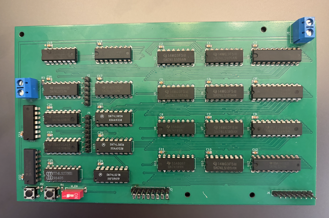
Current prototype supports:
Known issues:
Main subsystems:
analyzer_7400.circ — 74xx IC Implementation
ram_unit subcircuits.mem_64x8.analyzer_ttl.circ — Abstract Logic Implementation
More detailed documentation:
docs/                   Docs and architecture notes
images/                 Build photos and diagrams
pcb/                    KiCad PCB projects
simulations/            Logisim simulations
attiny-logic-analyzer/ Related MCU-based projectMain IC families/components:
If the project expands beyond basic TTL hardware, plans may include
MIT License
| Qty | Value | Footprint | References |
|---|---|---|---|
| 4 | C | Capacitor_THT:C_Disc_D7.0mm_W2.5mm_P5.00mm | C1, C2, C3, C4 |
| 3 | 74HC165 | Package_DIP:DIP-16_W7.62mm | U1, U2, U3 |
| 1 | ATtiny85 | Package_DIP:DIP-8_W7.62mm | U4 |
| 1 | Conn_01x04_Pin | Connector_PinHeader_2.54mm:PinHeader_1x04_P2.54mm_Vertical | J2 |
| 1 | Conn_01x24_Pin | Connector_PinHeader_2.54mm:PinHeader_1x24_P2.54mm_Vertical | J1 |
| 1 | R | Resistor_THT:R_Axial_DIN0207_L6.3mm_D2.5mm_P7.62mm_Horizontal | R1 |
| 1 | SW_Push | Button_Switch_THT:SW_PUSH_6mm | SW1 |
| 1 | Screw_Terminal_01x02 | TerminalBlock_Phoenix:TerminalBlock_Phoenix_MKDS-1,5-2-5.08_1x02_P5.08mm_Horizontal | J3 |
The 13 most common of 16 parts.
It measures 50.3 × 80.3 mm and has 2 copper layers, 1.6 mm thick.
16 parts, built around the ATTINY85-15M and 74HC165D. The full list of its parts is on this page, with links to each part's symbol and footprint where PCBKit's library has them.
From the TSJR/logic-analyzer repository on GitHub, at the commit this page was made from: the board is attiny-logic-analyzer/pcb/Logic Analyzer.kicad_pcb and its schematic attiny-logic-analyzer/pcb/.kicad_sch.kicad_sch. PCBKit opens the board in the browser, with nothing to install.
Its repository states no licence, so its author keeps all rights: ask TSJR before reusing the design.
TSJR/logic-analyzer
TTL logic analyzer built from 74xx logic and LED dot matrix display


TSJR/logic-analyzer
TTL logic analyzer built from 74xx logic and LED dot matrix display

cnlohr/ethertiny
A firmware-only half-duplex 10Base-T implementation for AVRs


Guiimartinho/routeai
LLM-Powered Electronic Design Automation Platform for PCB Design

rallekralle11/Tinyreflow
Inspired by afterearthltd's reflow plate, but using fewer and simpler components.

aleh/MIDIMonkey
Listens to MIDI messages on one pin and triggers drums on the others
