2 layers50.3 × 80.3 mm
Logic Analyzer
TSJR/logic-analyzer
TTL logic analyzer built from 74xx logic and LED dot matrix display
16 parts

 TSJR/logic-analyzer
TTL logic analyzer built from 74xx logic and LED dot matrix display
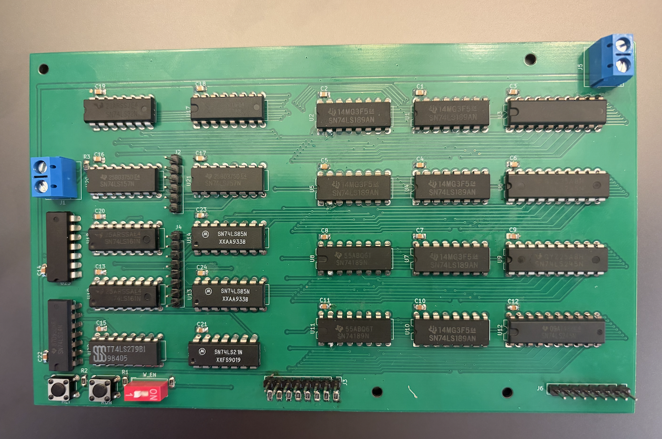
Memory subsystem is an open-source printed circuit board by TSJR, from the TSJR/logic-analyzer repository on GitHub. It is a 2-layer board of 162.6 × 97.3 mm with 73 parts on 137 nets, routed with 1,178 tracks and 278 vias.
It is built around the 74LS245SC, 74LS157PC and 74LS161DC, with the 74LS32SC, 74LS85DC and 74LS139PC among its other parts. Its parts include 24 capacitors, 24 ICs, 12 resistors and 6 connectors. It belongs with the sensors and measurement and lEDs and displays boards of this library.


Breadboard and PCB-based logic analyzer built from discrete 74xx TTL logic, SRAM, and multiplexed LED matrix displays.
This project aims to build a fully discrete logic analyzer without using a microcontroller. The analyzer captures digital bus states into SRAM and displays captured samples on multiplexed LED matrices.
Project is currently in a state of active prototyping.
*This repository also contains a closely related project using an MCU-based design with 24 channels.
Current prototype supports:
Known issues:
Main subsystems:
analyzer_7400.circ — 74xx IC Implementation
ram_unit subcircuits.mem_64x8.analyzer_ttl.circ — Abstract Logic Implementation
More detailed documentation:
docs/                   Docs and architecture notes
images/                 Build photos and diagrams
pcb/                    KiCad PCB projects
simulations/            Logisim simulations
attiny-logic-analyzer/ Related MCU-based projectMain IC families/components:
If the project expands beyond basic TTL hardware, plans may include
MIT License
| Qty | Value | Footprint | References |
|---|---|---|---|
| 24 | C | Capacitor_SMD:C_0805_2012Metric_Pad1.18x1.45mm_HandSolder | C1, C2, C10, C11, C12, C13, C14, C15, C16, C17, C18, C19, C20, C21, C22, C23 +8 |
| 12 | R | Resistor_SMD:R_0805_2012Metric_Pad1.20x1.40mm_HandSolder | R1, R2, R3, R4, R5, R6, R7, R8, R9, R10, R11, R12 |
| 8 | ~ | Package_DIP:DIP-16_W7.62mm | U1, U2, U4, U5, U7, U8, U10, U11 |
| 4 | 74LS245 | Package_DIP:DIP-20_W7.62mm | U3, U6, U9, U12 |
| 2 | 74LS157 | Package_DIP:DIP-16_W7.62mm | U20, U21 |
| 2 | 74LS161 | Package_DIP:DIP-16_W7.62mm | U18, U19 |
| 2 | 74LS32 | Package_DIP:DIP-14_W7.62mm | U16, U23 |
| 2 | 74LS85 | Package_DIP:DIP-16_W7.62mm | U13, U14 |
| 1 | 74LS139 | Package_DIP:DIP-16_W7.62mm | U17 |
| 1 | 74LS14 | Package_DIP:DIP-14_W7.62mm | U24 |
| 1 | 74LS21 | Package_DIP:DIP-14_W7.62mm | U15 |
| 1 | 74LS279 | Package_DIP:DIP-16_W7.62mm | U22 |
| 1 | Addr In | Connector_PinHeader_2.54mm:PinHeader_1x06_P2.54mm_Vertical | J2 |
| 1 | CLK | TerminalBlock_Phoenix:TerminalBlock_Phoenix_MKDS-1,5-2_1x02_P5.00mm_Horizontal | J1 |
| 1 | Data In | Connector_PinHeader_2.54mm:PinHeader_1x08_P2.54mm_Vertical | J3 |
| 1 | Data Out | Connector_PinHeader_2.54mm:PinHeader_1x08_P2.54mm_Vertical | J6 |
| 1 | HLT | Button_Switch_THT:SW_TH_Tactile_Omron_B3F-100x | HLT |
| 1 | Power | TerminalBlock_Phoenix:TerminalBlock_Phoenix_MKDS-1,5-2_1x02_P5.00mm_Horizontal | J5 |
| 1 | RUN | Button_Switch_THT:SW_TH_Tactile_Omron_B3F-100x | RUN |
| 1 | W_EN | Button_Switch_THT:SW_DIP_SPSTx01_Slide_9.78x4.72mm_W7.62mm_P2.54mm | W_EN |
| 1 | Word In | Connector_PinHeader_2.54mm:PinHeader_1x08_P2.54mm_Vertical | J4 |
The 69 most common of 73 parts.
It measures 162.6 × 97.3 mm and has 2 copper layers, 1.6 mm thick.
73 parts, built around the 74LS245SC, 74LS157PC, 74LS161DC and 74LS32SC. The full list of its parts is on this page, with links to each part's symbol and footprint where PCBKit's library has them.
From the TSJR/logic-analyzer repository on GitHub, at the commit this page was made from: the board is pcb/memory_subsystem/memory_subsystem.kicad_pcb and its schematic attiny-logic-analyzer/pcb/.kicad_sch.kicad_sch. PCBKit opens the board in the browser, with nothing to install.
Its repository states no licence, so its author keeps all rights: ask TSJR before reusing the design.
TSJR/logic-analyzer
TTL logic analyzer built from 74xx logic and LED dot matrix display


TSJR/logic-analyzer
TTL logic analyzer built from 74xx logic and LED dot matrix display

NeilsVintageComputers/1981_Aamber-Pegasus-2023-Revival
My first computer, this is a replica I produced from the original schematics using original old components.


MatanBright/8BitComputer
This is a simple programmable 8-bit computer that is built from scratch.


electrickery/VIO_MPF_I
Extended firmware for the 6845 based video card for the Microprofessor MPF-I(b)
