2 layers87 × 56 mm

 trihome/RasPi_NervesBOX5
An extension platform for the Raspberry Pi that mimics the functionality of a PLC.
NBoxRpi is an open-source printed circuit board by trihome, from the trihome/RasPi_NervesBOX repository on GitHub, published under the CC-BY-SA-4.0 licence. It is a 2-layer board of 68 × 86.9 mm with 95 parts on 70 nets, routed with 619 tracks and 62 vias.
It is built around the 74HC541D, MCP3002-I/P and TLP222AF, with the DS1307+, 1N4148W and FOD814A300W among its other parts. Its parts include 41 resistors, 16 diodes, 10 connectors, 9 ICs and 5 capacitors.


このボードは、産業用に使用される機器(例:24V駆動のスイッチ、センサー、リレーなど)をRaspberry Piへ接続できるようにします。
詳しくは、Qiitaの記事「Elixir/NervesでPLC(多機能リレー)を作ってみた」をご覧ください。
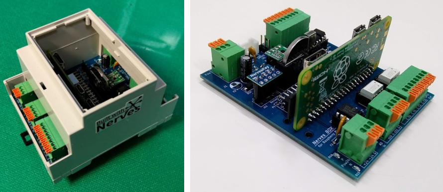
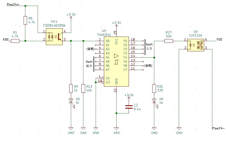
| 機能 | 仕様 | 補足 |
|---|---|---|
| 出力 | 4ch(フォトリレー絶縁) | シンク(NPN)・ソース(PNP)駆動切り替え可能。各chの動作確認LEDあり。 |
| 入力 | 4ch(フォトカプラ絶縁) | 〃 |
| AD変換 | 10bit 2ch | 非絶縁・入力保護のダイオード付き |
| 時刻保持 | リアルタイムクロックDS1307 | ボタン電池でバックアップ |
| GROVEコネクタ | あり、I2C x 1 | 5V電源タイプ |
| 外部UART端子 | あり x 1 | RaspberryPiのUARTに直結 |
| 電源 | 5V系/24V系は個別に供給 | それぞれポリスイッチ(過電流防止)あり |
J5, J7の接続
| 対応表 | GPIO(BCM表記) | 本機の端子 |
|---|---|---|
| 入力 | 12 | X0 |
| 〃 | 16 | X1 |
| 〃 | 20 | X2 |
| 〃 | 21 | X3 |
| 出力 | 6 | Y0 |
| 〃 | 13 | Y1 |
| 〃 | 19 | Y2 |
| 〃 | 26 | Y3 |
J2の接続
| 駆動したい方法 | Pow24+In | Pow24-In | D16 | D13 | X側COM端子 | Y側COM端子 | ||
|---|---|---|---|---|---|---|---|---|
| シンク | +24V | GND | → | 点灯 | 消灯 | GND | +24V | |
| ソース | GND | +24V | → | 消灯 | 点灯 | +24V | GND |
Manualをご覧ください。
| Qty | Value | Footprint | References |
|---|---|---|---|
| 14 | 10k | Resistor_SMD:R_0603_1608Metric_Pad1.05x0.95mm_HandSolder | R13, R14, R15, R16, R17, R18, R19, R20, R32, R33, R34, R35, R40, R41 |
| 10 | 4.7k | Resistor_SMD:R_0603_1608Metric_Pad1.05x0.95mm_HandSolder | R1, R2, R3, R4, R5, R6, R7, R8, R26, R31 |
| 8 | 1k | Resistor_SMD:R_0603_1608Metric_Pad1.05x0.95mm_HandSolder | R9, R10, R11, R12, R36, R37, R38, R39 |
| 8 | 330 | Resistor_SMD:R_0603_1608Metric_Pad1.05x0.95mm_HandSolder | R21, R23, R24, R25, R27, R28, R29, R30 |
| 4 | 1N4148W | Diode_SMD:D_SOD-123 | D1, D2, D3, D4 |
| 4 | FOD814A300W | Package_DIP:DIP-4_W7.62mm | PC1, PC2, PC3, PC4 |
| 4 | Gr | LED_SMD:LED_0603_1608Metric_Pad1.05x0.95mm_HandSolder | D5, D6, D7, D8 |
| 4 | MountingHole | MountingHole:MountingHole_3mm | MH1, MH2, MH3, MH4 |
| 4 | TLP222A | Package_DIP:DIP-4_W7.62mm | U6, U7, U8, U9 |
| 4 | Ye | LED_SMD:LED_0603_1608Metric_Pad1.05x0.95mm_HandSolder | D9, D11, D12, D14 |
| 3 | 0.1uF | Capacitor_SMD:C_0603_1608Metric_Pad1.05x0.95mm_HandSolder | C1, C2, C4 |
| 3 | Red | LED_SMD:LED_0603_1608Metric_Pad1.05x0.95mm_HandSolder | D10, D13, D16 |
| 2 | Pin Header 3 | Connector_PinHeader_2.54mm:PinHeader_1x03_P2.54mm_Vertical | J3, J9 |
| 2 | TB401-1-4-E | _my_kicad_symbol:Terminal_TB401-1-4-E | J2, J6 |
| 1 | 0.17A(MAX0.34) | Capacitor_THT:C_Disc_D5.0mm_W2.5mm_P5.00mm | F1 |
| 1 | 0.5A(MAX1A) | Capacitor_THT:C_Disc_D5.0mm_W2.5mm_P5.00mm | F2 |
| 1 | 100uF | Capacitor_THT:CP_Radial_D5.0mm_P2.50mm | C3 |
| 1 | 220uF | Capacitor_THT:CP_Radial_D5.0mm_P2.50mm | C5 |
| 1 | 32.768kHz | Crystal:Crystal_Round_D2.0mm_Vertical | Y1 |
| 1 | 470 | Resistor_SMD:R_0603_1608Metric_Pad1.05x0.95mm_HandSolder | R22 |
| 1 | 74HC541 | Package_SO:SO-20_5.3x12.6mm_P1.27mm | U4 |
| 1 | AE-PCA9306 | Package_DIP:DIP-8_W7.62mm | U1 |
| 1 | CH243-2032LF | _my_kicad_symbol:BatteryHolder_Keystone_CH74-2032LF | BT1 |
| 1 | DS1307+ | Package_SO:SO-8_3.9x4.9mm_P1.27mm | U3 |
| 1 | GROVE CONN | Connector:NS-Tech_Grove_1x04_P2mm_Vertical | J1 |
| 1 | MCP1703AT-3302E | Package_TO_SOT_SMD:SOT-23 | U5 |
| 1 | MCP3002 | Package_DIP:DIP-8_W7.62mm | U2 |
| 1 | MountingHole | Symbol:OSHW-Logo_5.7x6mm_SilkScreen | H1 |
| 1 | MountingHole | _my_kicad_symbol:CC-BY-SA | H2 |
| 1 | Pin Header 4 | Connector_PinHeader_2.54mm:PinHeader_1x05_P2.54mm_Vertical | J8 |
| 1 | RasPi CONN | _my_kicad_symbol:Connector_21602X20GRE | P1 |
| 1 | SBR1A40SA | Diode_SMD:D_SMA | D15 |
| 1 | TB401-1-3-E | _my_kicad_symbol:Terminal_TB401-1-8-E | J7 |
| 1 | TB401-1-3-E | _my_kicad_symbol:Terminal_TB401-1-3-E | J4 |
| 1 | TB401-1-8-E | _my_kicad_symbol:Terminal_TB401-1-8-E | J5 |

thawney/PedalPiV2
Pedal Pi V2 by Thawney is an all new and regularly maintained Pedal-Pi by electrosmash; a lo-fi programmable guitar pedal that works with the Raspberry Pi ZERO Board.

AnaviTechnology/anavi-gardening
ANAVI Gardening uHAT is an open source hardware add-on board for Raspberry Pi that helps you develop smart solutions for monitoring and growing plants.


RICCIARDI-Adrien/Cyclope
Raspberry Pi powered robot with camera live stream and 360° lidar.

ESCA47/thingamaPRO
Order at your own risk, even i fuck up too often. Maybe poke at me for help but for the most part you are on your own if you do decide to order these.

Jwray0/phori_2
Forked from the https://github.com/PhobGCC/PhobGCCv2-HW Project

plants-tech/Zinnia
fork of a fork of phob 2.x (Phob 2.x Official -> PhloraGCC -> Zinnia)
It measures 68 × 86.9 mm and has 2 copper layers, 1.6 mm thick.
95 parts, built around the 74HC541D, MCP3002-I/P, TLP222AF and DS1307+. The full list of its parts is on this page, with links to each part's symbol and footprint where PCBKit's library has them.
From the trihome/RasPi_NervesBOX repository on GitHub, at the commit this page was made from: the board is NBoxRpi.kicad_pcb. PCBKit opens the board in the browser, with nothing to install.
Its repository publishes it under the CC-BY-SA-4.0 licence: you may reuse it on that licence's terms (keep the author's notice, and for a copyleft licence share your changes alike).