Open-source Art-Net / sACN (E1.31) → DMX512 gateway for ESP32 / ESP32-S3 / Ethernet. Live web UI shows all 512 channels in real time, flags console conflicts, and drives galvanically-isolated DMX. Flash from your browser, no toolchain.
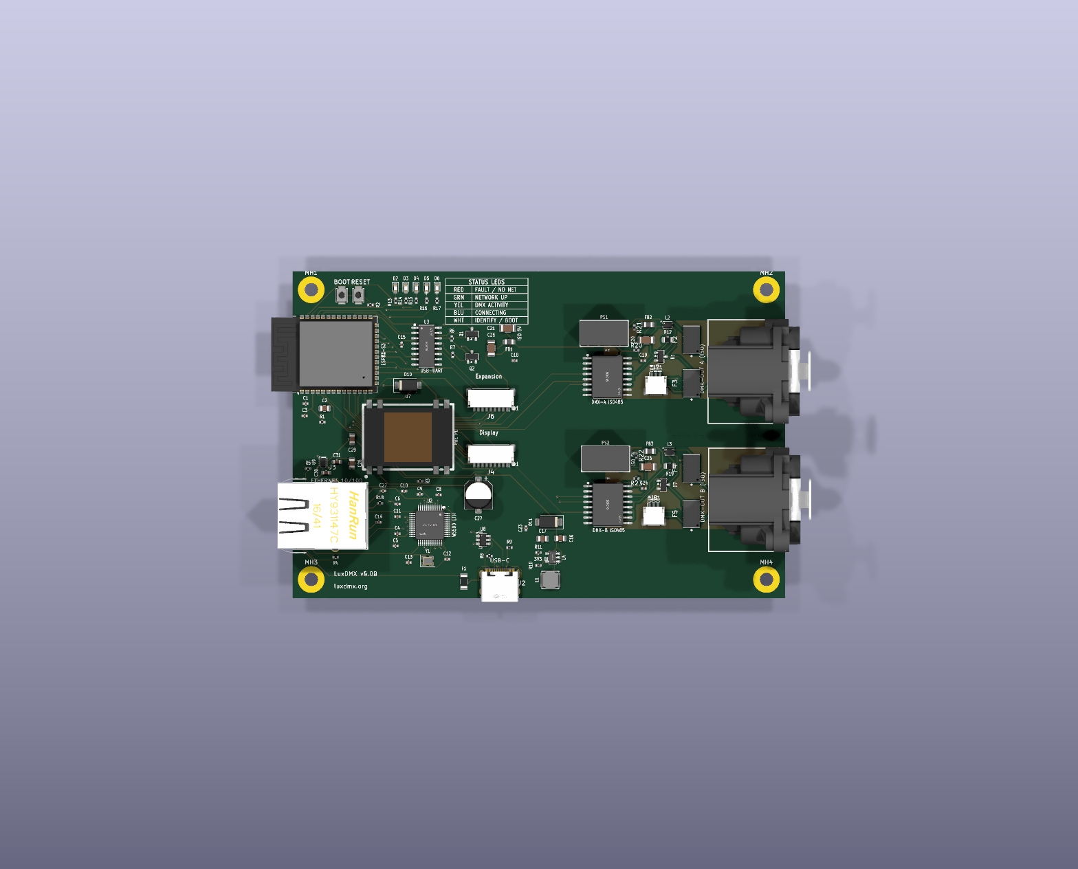
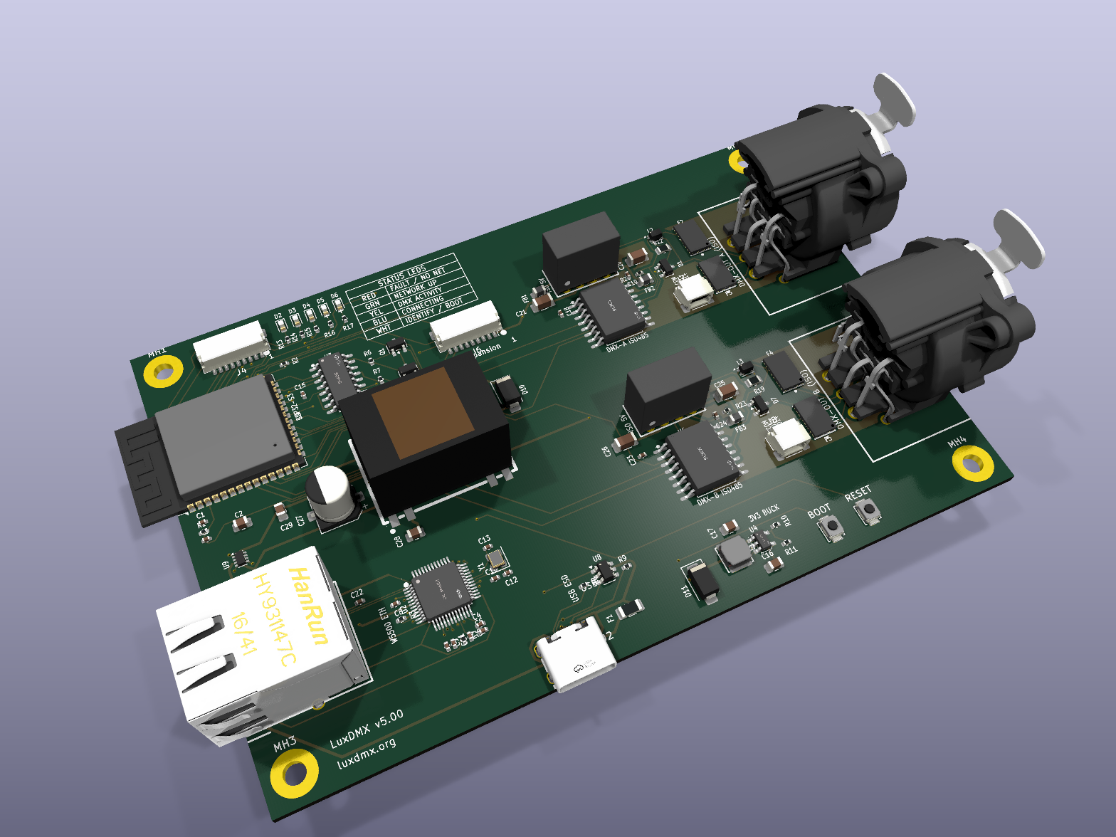
Luxdmx is an open-source printed circuit board by tombueng, from the tombueng/LuxDMX repository on GitHub. It is a 4-layer board of 119 × 79 mm with 97 parts on 86 nets, routed with 795 tracks and 173 vias.
It is built around the DP9900M-5V, ESP32-S3-WROOM-1-N8R2 and B0505S-1W, with the SY8089A, USBLC6-2SC6 and W5500 among its other parts. Its parts include 29 capacitors, 23 resistors, 9 diodes, 8 ICs and 8 connectors. It belongs with the interfaces and adapters and home automation and IoT boards and the ESP32 boards of this library.
[!NOTE]
v6 has not been fabricated yet. The board is on master, design-complete, and passes the full
scripted validation (DRC, isolation, SPICE, Ethernet skew, header parity; see VALIDATION.md).
An earlier spin of this design was built and came up working (rails, galvanic isolation, PoE
standalone, both DMX universes bit-exact, RDM 64/64 on both lines), but v6 carries changes that
have not been on physical copper yet: native USB instead of a CH340 bridge, TPS2116 priority mode,
a 3225 crystal package, and the J4/J6 header re-pin. Those are what the first v6 article has to
prove. Treat it as a prototype: the firmware on a plain ESP32 + an isolated RS-485 module is still
the longest-proven path (see the main README). The ruggedization pass (USB ESD, PTC fuse, +5V TVS,
a TPS2116 priority power mux, DMX common-mode chokes, ferrite supply filters), plated GND mounting
holes, wider power traces, and the DMX512-A "Protected" series-TBU front end are all in.
LuxDMX v6 — hardware
A compact, open-source Art-Net / sACN → galvanically-isolated DMX512 gateway, built around
an ESP32-S3 with both WiFi and wired Ethernet. Designed entirely as code (SKiDL netlist) and
routed by a fully-scripted, placement-driven pipeline — so the board regenerates itself from your
component placement, isolation barrier and all.
What problem does it solve?
Lighting consoles and media servers speak Art-Net or sACN (E1.31) over a network. Fixtures —
dimmers, moving heads, hazers, LED bars — speak DMX512 over an isolated RS-485 bus. LuxDMX sits
between them: it receives Art-Net/sACN over WiFi or Ethernet and emits a clean, opto-isolated DMX512
signal. It's the box that lets you drive a rack of conventional stage gear from QLab, a grandMA, or any
Art-Net source — without dragging a laptop and a USB-DMX dongle around backstage.
The whole device runs on a single ESP32-S3, fits on a board you can hold in your palm, and costs a few
dollars to fabricate at JLCPCB.
Headline design decisions (the "why")
Decision
Why
ESP32-S3 as the MCU
Plenty of GPIO, fast dual-core, native USB, mature Arduino/IDF support, and cheap. The N8R2 brings 8 MB flash + 2 MB PSRAM, and because that PSRAM is quad, it leaves GPIO35–37 free for the expansion header. Only the octal-PSRAM parts (R8 and up) wire GPIO33–37 to the memory and lose them.
W5500 SPI Ethernet (not the ESP's RMII)
The S3 has no built-in Ethernet MAC (unlike the original ESP32), so RMII/LAN8720 is physically impossible. The W5500 is a self-contained TCP/IP-offload Ethernet controller on SPI — the only practical wired-Ethernet path for the S3. Wired Ethernet matters: a packed venue's 2.4 GHz band is hostile, and a show can't drop frames.
Galvanically-isolated DMX
DMX runs long cables between gear sitting on different mains circuits with different ground potentials. Without isolation you get ground loops (noise, flicker) and, worse, fault currents that can destroy the gateway when something downstream shorts. Pro DMX gear is always isolated. We isolate both the data (ISO3086) and the power feeding it (B0505S DC-DC), so the DMX domain shares no copper with the logic side.
USB-C
Reversible, modern, and carries both power and native flashing — one cable to power and program.
4-layer PCB
A solid inner ground plane gives the W5500's Ethernet pairs a 100 Ω reference, tames EMI, and makes the dense routing actually fit. (More below.)
The components, in detail
Brains & networking
U1 — ESP32-S3-WROOM-1-N8R2(LCSC C2913204; 8 MB flash + 2 MB quad PSRAM) — the MCU + 2.4 GHz WiFi radio. Runs the Art-Net/sACN
receiver, the web UI, OTA updates, and the DMX engine. The PCB antenna hangs over the left board edge
(no copper underneath it — intentional, for radiation efficiency).
U2 — WIZnet W5500(C32843) + Y1 — 25 MHz crystal, 3225(C9006, CL = 12 pF, load caps C12/C13 = 18 pF C0G) + J3 — HY931147C PoE RJ45 MagJack(C91754) —
a complete 10/100 wired-Ethernet subsystem on SPI. The magjack integrates the isolation magnetics,
the link/activity LEDs, and an internal PoE rectifier (Mode A + Mode B → a single rectified DC pair
on pins 9/10 — see Power). (Ethernet is isolated by the magjack's transformers; the W5500's
current-mode TX center-tap is biased to 3V3 on the chip-side tap, independent of the PoE extraction
on the cable side.)
Isolated DMX output — two independent universes
Each universe is a self-contained galvanic island; the two share no copper with each other or the logic side.
U5 / U6 — TI ISO3086DWR(C183095) — the isolated RS-485 transceivers (one per universe). The DMX
driver and the logic that controls it are separated by a silicon isolation barrier rated for kilovolts.
Wired 2-wire (Y↔A, Z↔B bridged) for standard DMX512. Universe 1 on UART/port 1, universe 2 on port 2.
PS1 / PS2 — B0505S-1W(C7465127) — the isolated 5 V→5 V DC-DC modules powering the secondary
side of U5 / U6. Because both the data path and its power are isolated, each DMX connector shares no
ground with anything else.
D1 / D7 — SM712 TVS(C404012) + R12 / R19 — 120 Ω termination — per-universe surge protection
clamped to that universe's isolated ground, and the standard RS-485 line termination.
F2–F5 — Bourns TBU-CA065-200-WH(C913221) — a series high-speed protector on each DMX data line:
the DMX512-A "Protected" (E1.11 Annex C) front end. It blocks a sustained fault (someone plugging mains,
or up to ±42 V, into the XLR) in under a microsecond and self-recovers, so the SM712 only ever sees the
sub-microsecond transient. Full breakdown in E1.11_COMPLIANCE.md.
R20–R23 — 470 Ω fail-safe bias — hold each idle DMX pair in the RS-485 fail-safe state (needed for RDM).
J1 / J5 — XLR-5(C368501) — the two DMX output connectors (Neutrik NC5FAH), each living entirely on its isolated domain.
PoE (802.3af): the J3 magjack rectifies PoE internally and outputs DC on VPOE+/VPOE- →
U7 — SDAPO DP9900M-5V(C5380106), an isolated PD + DC-DC module (36–57 V in, regulated 5 V out,
1.5 kV isolation, class 0 ≈ 13 W — far more than this board's ~2–3 W). D10 — SMAJ58A(C110521) clamps
surges on the rectified rail. The module's -VDC becomes board GND; its +VDC is the PoE 5 V source.
5 V source select:U9 — TPS2116 power mux feeds the board +5V rail from either the PoE 5 V
(+5V_POE, on VIN1) or the USB-C 5 V (+5V_USB, through the F1 PTC, on VIN2), with no backfeed. It runs
in priority mode: MODE is tied to VIN1, so PoE wins whenever it is present and the board falls back
to USB only when PoE goes away. The PR1 divider (R24 = 30 kΩ / R25 = 10 kΩ) sets the VIN1 switchover
threshold to Vsw = 4.0 V (VREF 1.0 V × (30 + 10) / 10). Vsw is deliberately high, because VOUT tracks VIN1
down until the switch actually fires: at 4.0 V the +5V rail stays far above the ESP's ~2.8 V hang threshold
while PoE collapses. The pass-FET drop is only ~30 mV (vs ~0.4 V for a Schottky), so +5V stays ≈ 4.9 V on
USB and the B0505S / ISO3086 VCC2 rail clears its 4.5 V minimum across the whole USB range. Input caps
C30 / C31 (1 µF), bulk C29 (22 µF).
(The first article tied MODE/PR1 to GND, which is the default "higher voltage wins" mode. With two
near-equal 5 V sources that hunts, and a PoE→USB handover hung the board. Priority mode is that fix.)
U4 — SY8089 buck(C78988) + L1 — 2.2 µH — steps the muxed 5 V down to 3.3 V. The feedback
divider is R10 = 45.3 kΩ / R11 = 10 kΩ → 3.318 V (SPICE-verified). Powers everything on the logic side.
Programming & USB — native, no bridge chip
J2 — USB-C(C165948) — the USB data + power inlet, wired straight to the ESP32-S3's native USB
(USB_DM → IO19, USB_DP → IO20). The S3's USB-Serial-JTAG peripheral sits in ROM, so a bare USB-C cable
gives you the flashing port, the serial console and JTAG debug with no bridge chip. esptool resets
the chip over USB by itself, so there is no auto-reset circuit either.
R8 / R9 (5.1 kΩ) — the USB-C CC pulldowns (Rd) that tell a host to supply 5 V.
U8 — USBLC6-2SC6(C7519) — ESD clamp across the data pair. F1 — self-healing PTC on VBUS.
UART0 is free and broken out on J6 pins 7/8 (S3_TX / S3_RX), since nothing spends it on a bridge.
(The first article carried a CH340C (U3) plus a Q1/Q2 2-transistor auto-reset. Its collectors were
swapped, so EN and IO0 sat on the wrong transistors: flashing needed the manual BOOT-button dance, and a tool
asserting DTR or RTS alone could yank EN or IO0. Rather than re-wire it, the bridge and the reset circuit are
gone entirely, 6 parts fewer and 2 fewer part numbers to source.)
User interface & features
D2–D6 — 5 status LEDs (red/green/yellow/blue/white) wired straight to GPIOs (IO1/2/6/7/15): network
state, DMX activity, source-conflict, identify — at-a-glance status without a screen.
SW1 (BOOT) / SW2 (RST) — B3U-1000P tact switches (C231329). BOOT doubles as the config-portal /
factory-reset button in firmware; RST is a hard reset.
J4 — JST SH 1.0 mm 9-pin display header — an optional on-board OLED/TFT status panel connector.
Carries both I²C (SDA/SCL → for SSD1306/SH1106 mono OLEDs) and SPI (SCK/MOSI/CS/DC/RST → for
SSD1351 colour OLED / ST7789 TFT) on free, non-strapping GPIOs. JST SH is tiny and uses widely-available
pre-crimped cables. (Optional — populate only if you want the panel.)
J6 — JST SH 1.0 mm 9-pin expansion header — six free, non-strapping GPIOs for I²C / SPI / UART / PWM /
ADC add-ons, plus 3V3 and two grounds. Any pin muxes to whatever the S3's GPIO matrix supports, so the port
can run an I²C bus and a SPI bus at once. (Optional.)
Both headers share one power layout — on purpose
J4 and J6 are the same connector, so a cable fits either one. Their power pins are therefore
identical, and a validator (scripts/validate_header_parity.py, hard gate) keeps them that way:
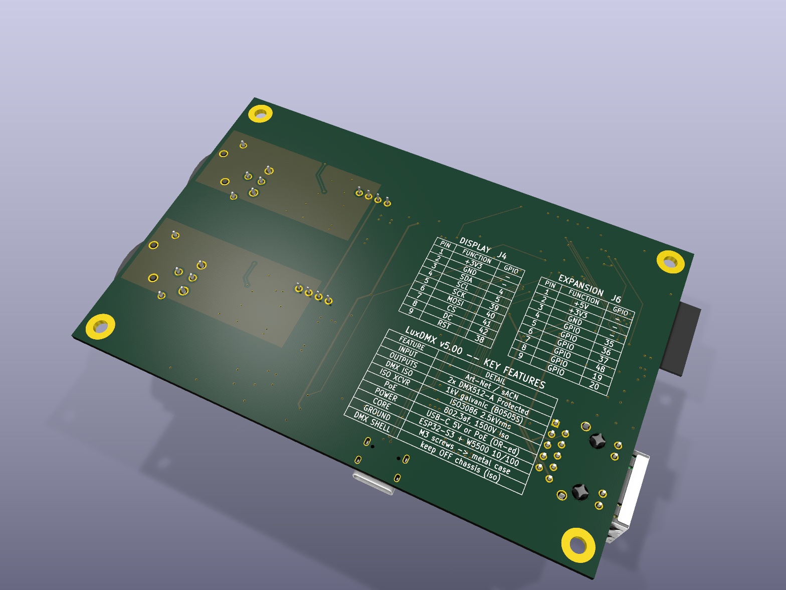
pin
J4 — display
J6 — expansion
1
+3V3
+3V3
2
GND
GND
3
SDA (IO4)
IO35
4
SCL (IO5)
IO36
5
SCK (IO39)
IO37
6
MOSI (IO40)
IO48
7
CS (IO41)
TX0 (IO43)
8
DC (IO42)
RX0 (IO44)
9
RST (IO38)
GND
Plug a cable into the wrong header and nothing dies: the module still gets correct power, and only 3V3 CMOS
signals land in the wrong places. A mis-plugged display sees GND on its RST and just sits quietly in reset.
There is no +5V on J6 — feed 5 V loads from your own supply. Dropping it is what lets both
headers share one power layout, and there was no free non-strapping GPIO left for a 7th signal
anyway, so pin 9 became a second ground. See
docs/display.md → Header safety.
🎚 Two independent, separately-isolated DMX512 universes — two XLR-5 outputs, each on its own
isolation island (RDM-capable transceivers); drive two universes from one box
⚡ Power-over-Ethernet (802.3af) — single Cat-5 cable for data and power; or USB-C — the TPS2116
mux gives PoE priority and falls back to USB, so either works and you can hot-swap between them
🖥 Optional OLED/TFT status display (I²C or SPI, via the JST header)
💡 5 status LEDs + BOOT/RST buttons
🔌 USB-C — single-cable power + native flashing, plus OTA updates
🟢 Open hardware, JLCPCB-assemblable
The 4-layer board & the isolation barrier
Stack-up: 4-layer, JLCPCB JLC04161H-7628 (1.6 mm; L1–L2 prepreg 0.2104 mm, Er 4.05 — the dielectric the Ethernet pairs are impedance-tuned to). The two inner layers are
ground-filled signal layers — not classic "power planes". That's deliberate: as signal layers the
autorouter will happily route ground (and fine-pitch escapes) to the inner copper, while the fill still
gives every trace a solid 0.21 mm-away reference. The result: clean ~100 Ω Ethernet pairs and good EMI.
Isolation: three barriers, all enforced by net-based rules in luxdmx.kicad_dru:
DMX universe 1 (GNDISO/VISO/DMX_A/DMX_B) and universe 2 (GNDISO2/VISO2/DMX2_A/DMX2_B)
are each held ≥ 4 mm from all other copper. Their barrier parts — PS1/PS2 (B0505S, 2.5 mm pitch)
and U5/U6 (ISO3086) — are courtyard-exempted (isolation internal/rated), like the USB-C pads.
PoE-hot (VPOE+/VPOE-, the magjack→module rectified rail) is held ≥ 2.5 mm from everything else;
the 1.5 kV PD isolation itself is internal to U7 (DP9900M) and J3 (magjack), so their courtyards
are exempt. The board's only galvanic tie to the PoE line is through the module + magjack magnetics.
The inner ground planes are carved (keepout rule-areas) around every isolated/hot region so no inner
copper crosses any barrier — scripts/rebuild_iso.py regenerates this for all three domains from
the live part positions.
Design-as-code & the routing pipeline
[!CAUTION]
Do not run the pipeline steps casually on the committed board. Everything in the list below that
touches the .kicad_pcb (sync_board, rebuild_iso, escape_connectors, autoroute_fr2,
cleanup_pads, normalize_silk, widen_eth, tighten_poe_void, finish_partial, route_tbu,
build_v3) rewrites it. The board as committed carries hand-made placement and silk edits that
those steps would wipe out. They are the tools for a deliberate re-route from a new placement, not a
"refresh". Re-running them by reflex is how you lose a day.
Always safe (read the board, never write it): scripts/luxdmx.py (writes only the netlist),
gen_schematic / gen_bom_from_board / gen_cpl / gen_gerbers (write only outputs), and every
validate_* gate.
The board is generated, not hand-drawn. scripts/luxdmx.py is a SKiDL
netlist — the single source of truth for every part and connection. From a placement, the rest is scripted
and adapts to wherever you put the parts:
text
0. python scripts/luxdmx.py            # SKiDL → luxdmx.net (only after editing the netlist source)
0b python scripts/sync_board.py          # add NEW/changed parts to the board, KEEPING existing placement,
                                 #   gridded in the enlarged area (scripts/build_v3.py = full from-scratch grid)
1. place / move parts in KiCad   →  save
2. python scripts/rebuild_iso.py         # regenerates inner GND planes + the two GNDISO pours + the three
                                 #   isolation keepouts (DMX1/DMX2/PoE) from LIVE positions — no hardcoded coords
3. python scripts/escape_connectors.py   # escapes the few fine-pitch connector pins to LOCKED vias
4. python scripts/autoroute_fr2.py       # Freerouting 2.2.4 routes the whole board, keeping locked escapes
5. python scripts/cleanup_pads.py        # mounting posts → NPTH, widen tight THT annular rings
Run everything with the KiCad 10 bundled Python (it ships pcbnew). scripts/autoroute_fr2.py drives
Freerouting 2.2.4, which needs Java 25+; the jar and a portable JDK live in tools/ (git-ignored).
Locked tracks survive every re-route (KiCad exports them as DSN (type fix)), so connector escapes only
get done once. Move a part, re-run — done.
Adding the dual-universe + PoE parts to an existing board:scripts/sync_board.py is the
incremental path — it keeps every already-placed footprint where it is, refreshes pad nets (e.g. J2's VBUS
moving onto +5V_USB), swaps J3 to the PoE magjack, and drops the brand-new parts (U6/PS2/J5/D7, U7/D10,
the new caps) in a grid on the right of the enlarged outline for you to place. Then run the normal
2→5 pipeline. scripts/build_v3.py remains the full from-scratch grid build if you'd rather re-place everything.
Fabricating it at JLCPCB
Everything you upload is already generated in this folder.
1 — Bare PCB
Go to jlcpcb.com → Add gerber file → upload luxdmx_gerbers.zip.
It auto-detects 4 layers. Set: Layers = 4, Thickness 1.6 mm, Impedance control =
JLC04161H-7628 stackup (the one the board's Ethernet impedance is designed for). Surface finish your choice (ENIG
recommended for the fine-pitch parts).
2 — Assembly (SMT)
Enable PCB Assembly, then upload:
BOM → luxdmx_BOM_jlcpcb.csv
CPL / pick-and-place → luxdmx_CPL.csv
In the BOM matching step, confirm each LCSC part (they're all pre-filled, every line in JLC stock). The
optional display / expansion headers J4 / J6 (JST SH 9-pin, C160408) are in the BOM — mark them Do
Not Populate if you don't want the on-board panel.
Review the placement preview — the CPL is rotation/position-corrected by scripts/gen_cpl.py, so parts
should sit correctly. The ESP32-S3's antenna intentionally overhangs the left edge.
3 — Through-hole parts
The XLRs (J1, J5), USB-C (J2), PoE MagJack (J3), B0505S modules (PS1, PS2) and the DP9900M PoE module (U7)
are through-hole / module parts. Either add JLCPCB's through-hole assembly or hand-solder them — they're all
large, easy joints.
Cost ballpark
4-layer, this size, 5 pcs ≈ a few dollars for the bare boards; SMT assembly adds the parts + a setup
fee. A complete, assembled prototype lands well under typical hobby budgets.
LCSC/easyeda footprints + 3D models for the specific parts
tools/
Freerouting 2.2.4 jar + portable JDK 25 (git-ignored — see Toolchain)
board-pcb-1.png · board3d-1.png · board3d-2.png
layout + 3D renders
Status
Design-complete, fully validated, and the first spin is being fabricated. Not yet bench-tested on
real hardware, so treat this first spin as a prototype.
The board (two isolated DMX universes + PoE, 119 × 79 mm, 4 corner plated M3 mounting holes) is
fully routed (0 unrouted, 0 unconnected) and passes the scripted validation:
DRC: 3 clearance waivers only (2× W5500 0.5 mm-pitch escapes at 0.174 mm, USB-C CC2 at 0.160 mm),
all above JLCPCB's 0.0889 mm floor. 0 silk-over-pad, 0 courtyard overlaps, 0 dangling vias.
Isolation: 0 violations of the two 4 mm DMX and the 2.5 mm PoE creepage rules (luxdmx.kicad_dru).
Power: SPICE-verified. The TPS2116 priority mux holds +5V at ~4.9 V on USB, so the B0505S / ISO3086
VCC2 stays above its 4.5 V minimum across the whole USB range (>= 4.6 V even at a sagging 4.7 V VBUS);
buck output 3.318 V.
Ethernet: diff-pair skew TX 0.35 mm / RX 2.14 mm, well inside the 100BASE-TX margin.
See VALIDATION.md for the full matrix. Open items to confirm before fab (none electrical-blocking):
PoE magjack pinout. J3's pin/function map (1=RD- 2=RD+ 3=RX-CT 4=TX-CT 5=TD- 6=TD+ 9=V+ 10=V-,
LEDs 11-14) comes from the HY931147C datasheet via the pulled EasyEDA model. Confirm the TX/RX
pair assignment and LED anode/cathode against the datasheet before fab; a swapped TX/RX pair means
no Ethernet link (W5500 has no auto-MDIX). HY931147C omits Bob-Smith termination; HanRun HR861153C
(C19724782) is a pin-different drop-in that includes it for extra signal-integrity margin.
DP9900M LCSC SKU — confirm the 5 V / 1.8 A part, its on-module 802.3af detection/classification and
pin order. Min load is 100 mA; the running board draws well over that, so no bleeder is needed.
Cosmetic silk (37 warnings, all mask-protected) to clear in a short GUI pass or waive at upload.
Firmware support
Both board-specific firmware features ship in the released esp32s3dev build (the board has no
dedicated env — it is an ESP32-S3 + W5500 with a fixed pin map; flash that build and pick the
LuxDMX v6 board template in /config). See platformio.ini. Built on
arduino-esp32 v3 / ESP-IDF 5.5:
W5500 SPI-Ethernet driver.ETH.begin(ETH_PHY_W5500, …) registers the W5500 as an lwIP
netif, so the existing AsyncWebServer / Art-Net / sACN / OTA stack runs over wired Ethernet
unchanged — on SCLK=IO12, MOSI=IO11, MISO=IO13, CS=IO10, INT=IO14, RST=IO9 (SPI3 host),
selected by the USE_ETH_SPI build flag. This requires arduino-esp32 v3 (v2.x has no
ETH_PHY_W5500), which is why the whole firmware moved to the v3 framework via the
pioarduino platform.
5 discrete status LEDs. A new ledType=3 model drives all five LEDs simultaneously —
R=IO1 no network · G=IO2 network up · Y=IO6 DMX activity ·
B=IO7 source conflict · W=IO15 identify. Pins are configurable in /config.
Two DMX outputs (firmware already supports MAX_OUTPUTS = 2). Universe 1 is on UART/port 1
(TX=IO17, RX=IO18, DE=IO8); the new universe 2 is on UART/port 2 — wire to TX=IO16, RX=IO21,
DE/RTS=IO47. Output #2 ships disabled by default; enable it and set those pins in /config
(out#2: port=2 tx=16 rx=21 rts=47). All pins are runtime-configurable, so no firmware rebuild is needed.
The RJ45 MagJack's link/act LEDs are driven by the W5500 itself — no firmware needed.
Build caveats (both handled, but worth knowing for a clean checkout / CI):
esp_dmx 4.1.0 on ESP-IDF 5.5 — needs a small fix (the removed uart_periph_signal[].module
field, plus the older UART2 guard). Applied automatically at build time by
extra_scripts.py — no manual step.
pioarduino toolchain installer — release 55.03.39's Xtensa toolchain archive trips
idf_tools.py (do_strip_container_dirs: "expected 1 entry, got ['package.json', …]"), which
leaves the compiler uninstalled. This is an installer bug, not a repo issue; it needs a
one-time host patch (ignore the stray package.json) or a different platform pin. CI on this
pinned release needs the same handling.
Open-source Art-Net / sACN (E1.31) → DMX512 gateway for ESP32 / ESP32-S3 / Ethernet. Live web UI shows all 512 channels in real time, flags console conflicts, and drives galvanically-isolated DMX.
Open-source Art-Net / sACN (E1.31) → DMX512 gateway for ESP32 / ESP32-S3 / Ethernet. Live web UI shows all 512 channels in real time, flags console conflicts, and drives galvanically-isolated DMX.
Open-source Art-Net / sACN (E1.31) → DMX512 gateway for ESP32 / ESP32-S3 / Ethernet. Live web UI shows all 512 channels in real time, flags console conflicts, and drives galvanically-isolated DMX.
Open-source Art-Net / sACN (E1.31) → DMX512 gateway for ESP32 / ESP32-S3 / Ethernet. Live web UI shows all 512 channels in real time, flags console conflicts, and drives galvanically-isolated DMX.
🚧 WIP – not yet manufactured or tested. KiCad PCB (one per door) connecting Hörmann series 4 garage door operators (ProMatic/SupraMatic, BUS/RJ12) to Loxone via ESP32-S3 and Wi-Fi.
It measures 119 × 79 mm and has 4 copper layers, 1.6 mm thick.
What parts does the Luxdmx use?
97 parts, built around the DP9900M-5V, ESP32-S3-WROOM-1-N8R2, B0505S-1W and SY8089A. The full list of its parts is on this page, with links to each part's symbol and footprint where PCBKit's library has them.
Where can I download the Luxdmx KiCad files?
From the tombueng/LuxDMX repository on GitHub, at the commit this page was made from: the board is hardware/luxdmx.kicad_pcb and its schematic hardware/luxdmx.kicad_sch. PCBKit opens the board in the browser, with nothing to install.
Can I use the Luxdmx design in my own project?
Its repository states no licence, so its author keeps all rights: ask tombueng before reusing the design.