4 layers81 × 60 mm

 tjko/fanpico239
Fanpico: Open Source Programmable PWM (PC) Fan Controller
Fanpico is an open-source printed circuit board by tjko, from the tjko/fanpico repository on GitHub, published under the GPL-3.0 licence. It is a 4-layer board of 82.5 × 81.5 mm with 113 parts on 74 nets, routed with 630 tracks and 47 vias.
It is built around the SN74AHCT126D, BAT54CL and 2N7002K. Its parts include 36 diodes, 27 resistors, 17 capacitors, 14 connectors and 4 ICs. It belongs with the home automation and IoT and computers and single-board computers boards and the RP2040 boards of this library.



Fanpico is a smart PWM (PC) fan controller based around Raspberry Pi Pico (RP2040 MCU). Fanpico operates as standalone controller that can be configured and left running. It does not require any drivers and doesn't care what OS is being used. FanPico is an Open-source hardware (OSHW) project.


Serial "Console". Primary method for configuring/monitoring FanPico units is via (USB) Serial console (some units also have 3.3V TTL Serial connection).
Desktop application (that polls FanPico using SCPI commands over the console connection): FanPico Monitor
Web Interface (available when using Pico W) over WiFi

For more documentation check FanPico Wiki
I would like to thank following sponsors, who have helped FanPico project:
Currently Fanpico is available as a DIY project. Check discussion forums for places to purchase Kits or PCBs: Places to Purchase FanPico
(Instructions for building the kit are in FanPico Wiki)
However, if there is sufficient interest, then ready-made units may be made available for sale. If you'd be interested in purchasing FanPico pease indicate your interest here: FanPico Forum
You can upload the Kerber files (found under boards directory) to your favorite PCB maker website and get your boards produced in matter of days. Component list (BOM or bill of materials) is found under boards directory as well along with the electrical schematics.
NOTE, check discussions forum for giveaways for free PCBs.
If you are member of press (or YouTuber) and would like to review/test Fanpico. Please contact me via email.
Fanpico is Open Source Hardware, reference design is provided for the "0804" model (8 fan outputs and 4 motherboard fan inputs), and "0804D" model that adds OLED display support (hence the "D" suffix).
Additional models with different combinations of fan inputs/outputs could be easily designed (takining into account limitations of Raspberry Pi Pico I/O limits). New and improved PCB models/designs are most welcome.
Model "0840D" with (with right-angle connectors and DC power connector):

Model "0804" without display (with straight connectors):
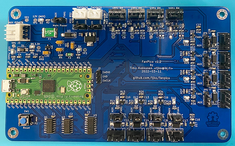
Fanpico (reference design) utilizes all available I/O pins on a Raspberry Pi Pico.
To help design and test Fanpico couple other projects were born:
Projects based on FanPico firmware:
Currently following models are available:
| Model | Fans (Outputs) | MB Fan (Inputs) | External Temperature Sensors | Display | Notes |
|---|---|---|---|---|---|
| FANPICO-0804 | 8 | 4 | 2 | N | First publicly available board (reference design). |
| FANPICO-0804D | 8 | 4 | 2 | Y | Support for OLED (128x64 or 128x128) displays |
| FANPICO-0401D | 4 | 1 | 2 | Y | Adds QWIIC and 1-Wire connectors. |
| FANPICO-0200 | 2 | 0 | 2 | Y | OLED display supported via QWIIC connector. PCB under development. |
(all boards have one additional 'on-board' temperature sensor on the RP2040 MCU itself)
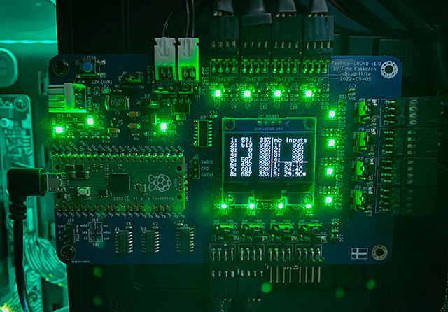
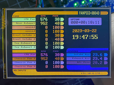
Models ending with "D" have connector to attach OLED display module to see 'real-time' status of fans and temperatures.
OLED panel directly mounted on the PCB:
LCD Panel attached via a short cable:
Following accessories are available:
| Model | Info |
|---|---|
| OLED-Adapter | Mounting adapter for OLED boards with different pinouts. |
| Power-Board | Adapter for using high-power fans with FanPico. |
Firmware is developed in C using the Pico SDK. Pre-compiled firmware is released when there is new major features or bug fixes.
Latest pre-compiled firmware image can be found here: Releases
To get latest firmware with latest updates/fixes you must compile the firmware from the sources.
Firmware can be installed via the built-in UF2 bootloader on the Raspberry Pi Pico or using the debug header with Picoprobe, etc...
Each release (zip file) contains multiple different firmware files. Make sure to select firmware for the board you're using and for the pico model ("pico_w" if using Pico W).
Firmware file names have format: fanpico-<board_model>-<pico_model>.uf2
fanpico-0401D-pico.uf2
fanpico-0401D-pico_w.uf2
fanpico-0804-pico.uf2
fanpico-0804-pico_w.uf2
fanpico-0804D-pico.uf2
fanpico-0804D-pico_w.uf2Firmware upgrade steps:
Raspberry Pi Pico C/C++ SDK is required for compiling the firmware:
Pico SDK must be installed working before you can compile fanpico.
Instructions on installing Pico SDK see: Getting started with Raspberry Pi Pico
(Make sure PICO_SDK_PATH environment variable is set)
Create some directory for building fanpico ('src' used in this example):
$ mkdir src
$ cd src
$ git clone https://github.com/tjko/fanpico.git
$ git submodule update --init --recursiveTo build fanpico firmware, first create a build directory:
$ cd fanpico
$ mkdir build
Select which board to build firmware for (default is "0804") and which Pico is to be used (default is "pico"):
$ cd build
$ cmake -DFANPICO_BOARD=0804D -DPICO_BOARD=pico_w ..
Then compile fanpico:
$ make -jAfter successful compile you should see firmware binary in the build directory: subdirectory:
$ ls *.uf2
fanpico.uf2
If you have picotool installed you can check the firmware image information:
$ picotool info -a fanpico.uf2
File fanpico.uf2 family ID 'rp2040':

Program Information
 name:              fanpico
 version:           1.7.6
 web site:          https://kokkonen.net/fanpico/
 description:       FanPico-0804D - Smart PWM Fan Controller
 features:          USB stdin / stdout
 boot settings:     bootdelay = 0
                    safemode = 0
 binary start:      0x10000000
 binary end:        0x1012edc0
 embedded drive:    0x101c0000-0x10200000 (256K): littlefs

Fixed Pin Information
 0:                 TX (Serial) / MISO (SPI)
 1:                 RX (Serial) / CS (SPI)
 2:                 SDA (I2C) / SCK (SPI)
 3:                 SCL (I2C) / MOSI (SPI)
 4:                 Fan1 PWM signal (output)
 5:                 Fan2 PWM signal (output)
 6:                 Fan3 PWM signal (output)
7: Fan4 PWM signal (output)| Qty | Value | Footprint | References |
|---|---|---|---|
| 9 | 0.1uF | Capacitor_SMD:C_0603_1608Metric_Pad1.08x0.95mm_HandSolder | C1, C4, C6, C11, C22, C24, C26, C29, C32 |
| 9 | 10k | Resistor_SMD:R_0603_1608Metric_Pad0.98x0.95mm_HandSolder | R5, R7, R13, R15, R37, R40, R43, R50, R51 |
| 9 | 3.3V TVS | Diode_SMD:D_SOD-323_HandSoldering | D7, D13, D14, D16, D17, D18, D19, D23, D29 |
| 6 | 12V TVS | Diode_SMD:D_SOD-323_HandSoldering | D2, D15, D20, D21, D22, D26 |
| 6 | LED 0805 (green) | LED_SMD:LED_0805_2012Metric_Pad1.15x1.40mm_HandSolder | D4, D5, D6, D8, D12, D32 |
| 5 | 5V TVS | Diode_SMD:D_SOD-323_HandSoldering | D11, D33, D34, D35, D36 |
| 5 | ES1D 1A 200V | Diode_SMD:D_SMA_Handsoldering | D3, D10, D25, D28, D31 |
| 4 | 1nF | Capacitor_SMD:C_0603_1608Metric_Pad1.08x0.95mm_HandSolder | C10, C21, C23, C25 |
| 4 | 49.9k | Resistor_SMD:R_0603_1608Metric_Pad0.98x0.95mm_HandSolder | R9, R10, R12, R16 |
| 4 | 680 | Resistor_SMD:R_0603_1608Metric_Pad0.98x0.95mm_HandSolder | R14, R38, R41, R44 |
| 4 | BAT54(C) | FanPico:D_SOT-23_ANK | D9, D24, D27, D30 |
| 4 | MountingHole_Pad | MountingHole:MountingHole_3.2mm_M3_Pad_Via | H1, H2, H3, H4 |
| 3 | 10uF 16V | Capacitor_Tantalum_SMD:CP_EIA-3216-18_Kemet-A_Pad1.58x1.35mm_HandSolder | C7, C8, C30 |
| 3 | 1k | Resistor_SMD:R_0603_1608Metric_Pad0.98x0.95mm_HandSolder | R1, R4, R11 |
| 2 | 0 | Resistor_SMD:R_0603_1608Metric_Pad0.98x0.95mm_HandSolder | R49, R55 |
| 2 | 2N7002K | Package_TO_SOT_SMD:SOT-23 | Q1, Q2 |
| 2 | 330 | Resistor_SMD:R_0603_1608Metric_Pad0.98x0.95mm_HandSolder | R3, R48 |
| 1 | 1-Wire | TerminalBlock_TE-Connectivity:TerminalBlock_TE_282834-3_1x03_P2.54mm_Horizontal | J5 |
| 1 | 1-Wire PullUp Enable | Connector_PinHeader_2.54mm:PinHeader_1x02_P2.54mm_Vertical | JP12 |
| 1 | 10uF 25V | Capacitor_Tantalum_SMD:CP_EIA-3528-12_Kemet-T_Pad1.50x2.35mm_HandSolder | C5 |
| 1 | 4.7k | Resistor_SMD:R_0603_1608Metric_Pad0.98x0.95mm_HandSolder | R2 |
| 1 | 4.99k | Resistor_SMD:R_0603_1608Metric_Pad0.98x0.95mm_HandSolder | R6 |
| 1 | DNF | Resistor_SMD:R_0603_1608Metric_Pad0.98x0.95mm_HandSolder | R54 |
| 1 | Fan1 Output | Connector:FanPinHeader_1x04_P2.54mm_Vertical | J8 |
| 1 | Fan2 Output | Connector:FanPinHeader_1x04_P2.54mm_Vertical | J12 |
| 1 | Fan3 Output | Connector:FanPinHeader_1x04_P2.54mm_Vertical | J13 |
| 1 | Fan4 Output | Connector:FanPinHeader_1x04_P2.54mm_Vertical | J14 |
| 1 | Floppy Power Connector | FanPico:TE 171826-4 Floppy 4-pin Combo | J1 |
| 1 | I2C (OLED ALT) | Connector_PinSocket_2.54mm:PinSocket_1x04_P2.54mm_Vertical | J2 |
| 1 | I2C (OLED) | Connector_PinSocket_2.54mm:PinSocket_1x04_P2.54mm_Vertical | J3 |
| 1 | LCD (SPI) | Connector_PinHeader_2.54mm:PinHeader_2x05_P2.54mm_Vertical | J18 |
| 1 | LM4040DBZ-3 | Package_TO_SOT_SMD:SOT-23 | U6 |
| 1 | MB Fan1 Input | Connector:FanPinHeader_1x04_P2.54mm_Vertical | J4 |
| 1 | Pico | FanPico:RPi_Pico_PicoW_SMD_TH | U4 |
| 1 | Polyfuse 0.5A | Fuse:Fuse_1206_3216Metric_Pad1.42x1.75mm_HandSolder | F2 |
| 1 | Polyfuse 1.5A | Fuse:Fuse_2920_7451Metric_Pad2.10x5.45mm_HandSolder | F3 |
| 1 | Polyfuse 2A | Fuse:Fuse_2920_7451Metric_Pad2.10x5.45mm_HandSolder | F1 |
| 1 | Power Selector | Connector_PinHeader_2.54mm:PinHeader_1x03_P2.54mm_Vertical | JP1 |
| 1 | QWIIC | Connector_JST:JST_SH_SM04B-SRSS-TB_1x04-1MP_P1.00mm_Horizontal | J6 |
| 1 | SM5819PL 1A 40V | Diode_SMD:D_SMA | D1 |
| 1 | SN74AHCT126 | Package_SO:TSSOP-14_4.4x5mm_P0.65mm | U1 |
| 1 | SPX1117-ADJ | Package_TO_SOT_SMD:SOT-223-3_TabPin2 | U5 |
| 1 | SW_Push | FanPico:SW_PUSH_6mm_SMD_2 | SW1 |
| 1 | Sensor1 | Connector_JST:JST_XH_B2B-XH-A_1x02_P2.50mm_Vertical | J16 |
| 1 | Sensor2 | Connector_JST:JST_XH_B2B-XH-A_1x02_P2.50mm_Vertical | J17 |
| 1 | Serial Console (TTL) | Connector_PinHeader_2.54mm:PinHeader_1x03_P2.54mm_Vertical | J19 |
The 110 most common of 113 parts.

tjko/fanpico
Fanpico: Open Source Programmable PWM (PC) Fan Controller

tjko/fanpico
Fanpico: Open Source Programmable PWM (PC) Fan Controller

punkfab/pcb-corpus
235 real KiCad boards from open-source hardware repositories, prepared as a placement and routing benchmark


Bellafaire/ESP32-Smart-Watch
An open source smartwatch based on the ESP32 compatible with the Arduino IDE.


AaronC81/delta-pico
Powerful scientific calculator based on the Raspberry Pi Pico

avenhaus/SO-ARM100-Encoders
It explores to use much cheaper magnetic encoders for the Leader Arm instead of the regular servos. These dummy servos are also much easier to move manually, as there is no gear train that needs to back drive the servo…

It measures 82.5 × 81.5 mm and has 4 copper layers, 1.6 mm thick.
113 parts, built around the SN74AHCT126D, BAT54CL and 2N7002K. The full list of its parts is on this page, with links to each part's symbol and footprint where PCBKit's library has them.
From the tjko/fanpico repository on GitHub, at the commit this page was made from: the board is boards/fanpico-0401D/kicad/fanpico.kicad_pcb and its schematic boards/fanpico-0200/kicad/extra_fan_channel.kicad_sch. PCBKit opens the board in the browser, with nothing to install.
Its repository publishes it under the GPL-3.0 licence: you may reuse it on that licence's terms (keep the author's notice, and for a copyleft licence share your changes alike).