2 layers77.7 × 159.8 mm
Delta pico
AaronC81/delta-pico
Powerful scientific calculator based on the Raspberry Pi Pico
73 parts57MIT

 AaronC81/delta-pico57
Powerful scientific calculator based on the Raspberry Pi Pico
Delta pico is an open-source printed circuit board by AaronC81, from the AaronC81/delta-pico repository on GitHub, published under the MIT licence. It is a 2-layer board of 77.7 × 166.3 mm with 84 parts on 98 nets, routed with 535 tracks and 48 vias.
It is built around the PCF8574AP, 24LC16B/P and 2N7002K. Its parts include 31 diodes, 31 switches, 5 resistors, 5 connectors and 4 ICs. It belongs with the RP2040 boards of this library.


The Delta Pico is a powerful scientific calculator built around the Raspberry Pi Pico.
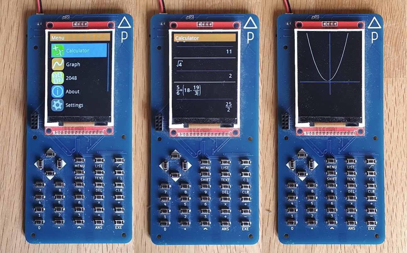
A follow-on project from my Delta M0, this calculator is much larger and significantly more capable, with a 2.8" 240x320 colour display and 30 keys.
The Delta Pico is powered by the rbop mathematical engine, for gorgeous textbook-style input.
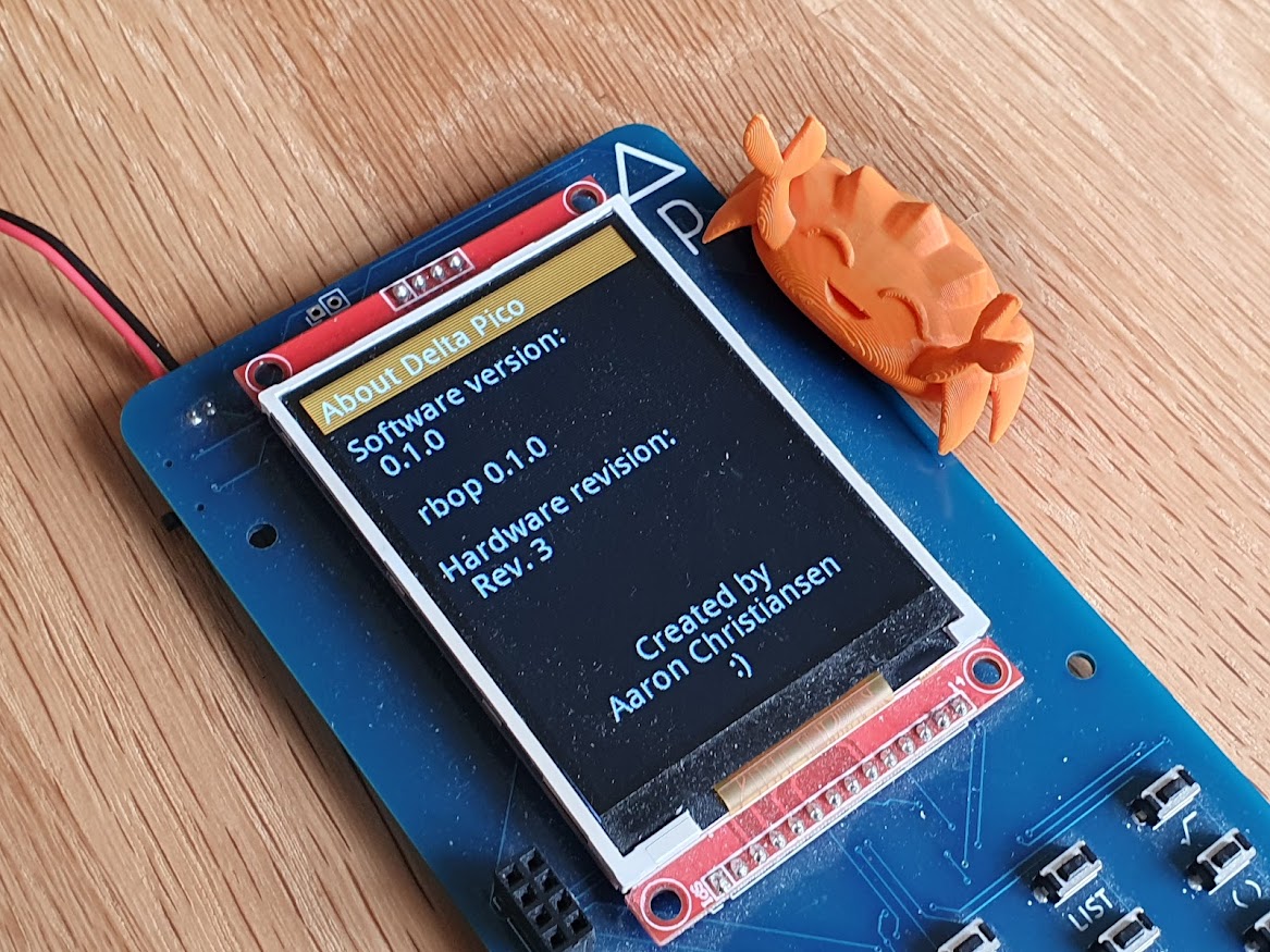
The Delta Pico's software is written in Rust. The hardware abstraction layer is separate to the user software, theoretically allowing the operating system to run on other hardware which supports embedded Rust!
You will likely need a bleeding-edge checkout of rbop, so you should check this
out too and adjust the path in rust/Cargo.toml accordingly.
This project has a dependency on FontForge, which is used for compiling fonts
into bitmaps. Install FontForge, and then set the DELTA_PICO_FFPYTHON
environment variable to point to its included ffpython executable. If you've
done this right, you should be able to run $DELTA_PICO_FFPYTHON in your
terminal (or %DELTA_PICO_FFPYTHON% on Windows) and get a Python interactive
prompt.
The build script also uses elf2uf2-rs to flash software to the Pico, so be sure to install this.
With all of the above dependencies sorted, cd into rust-hal and run:
cargo runWith a Pico connected in bootloader mode, this should build the project and flash it onto your Pico.
The KiCad files for the Delta Pico hardware can be found in the cad directory.
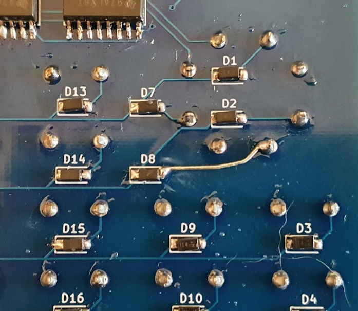
There is one error with the first hardware revision; a missing trace in the button matrix, between the down arrow button and diode D8. This can be easily fixed with a small piece of wire:
( key has been removed and merged into the ) key to form a single ( ) key
( key, there is a new TEXT key
This repository is licensed entirely under the MIT License, except
for font/DroidSans.ttf, which is sourced from Adobe Fonts and licensed under
the Apache License.
| Qty | Value | Footprint | References |
|---|---|---|---|
| 30 | D | Diode_SMD:D_SOD-123 | D1, D2, D10, D11, D12, D13, D14, D15, D16, D17, D18, D19, D20, D21, D22, D23 +14 |
| 30 | SW_Push | PTS636SL43LFS:PTS636SL43LFS | SW2, SW10, SW11, SW12, SW13, SW14, SW15, SW16, SW17, SW18, SW19, SW20, SW21, SW22, SW23, SW24 +14 |
| 5 | 10k | Resistor_SMD:R_0603_1608Metric_Pad0.98x0.95mm_HandSolder | R1, R2, R3, R4, R5 |
| 2 | PCF8574A | Package_SO:SOIC-16W_7.5x10.3mm_P1.27mm | U1, U2 |
| 1 | 24LC16 | Package_SO:SOIC-8_3.9x4.9mm_P1.27mm | U4 |
| 1 | 2N7002K | Package_TO_SOT_SMD:SOT-23 | Q1 |
| 1 | Conn_01x02 | Connector_JST:JST_PH_S2B-PH-K_1x02_P2.00mm_Horizontal | J1 |
| 1 | Conn_01x02 | Connector_PinHeader_2.54mm:PinHeader_1x02_P2.54mm_Vertical | J5 |
| 1 | Conn_01x04 | Connector_PinHeader_2.54mm:PinHeader_1x04_P2.54mm_Vertical | J4 |
| 1 | Conn_01x08 | Connector_PinHeader_2.54mm:PinHeader_2x04_P2.54mm_Vertical | J3 |
| 1 | Conn_01x14 | Connector_PinHeader_2.54mm:PinHeader_1x14_P2.54mm_Vertical | J2 |
| 1 | D_Schottky | Diode_SMD:D_SOD-123 | D31 |
| 1 | Pico | RPi_Pico:RPi_Pico_SMD_TH | U3 |
| 1 | SW_SPDT | Button_Switch_SMD:SW_SPDT_CK-JS102011SAQN | SW1 |
| 1 | SolderJumper_2_Open | Jumper:SolderJumper-2_P1.3mm_Open_RoundedPad1.0x1.5mm | JP1 |
The 78 most common of 84 parts.
AaronC81/delta-pico
Powerful scientific calculator based on the Raspberry Pi Pico

AaronC81/delta-pico
Powerful scientific calculator based on the Raspberry Pi Pico

terjeio/CNC_Breakout_Nucleo64
CNC breakout for STM324F411 and ST32F446 development boards

terjeio/CNC_Boosterpack
A BoosterPack that provides 3-axis motor support for some TI LaunchPads

RoMeLaUCLA/romela-motor-driver
Motor driver PCB and firmware designed for RoMeLa actuators.

markus-k/led-controller-hardware
KiCAD schematics and design files for my LED controller.


capconix/PiADC2
PiADC open source project successor, the PiADC2 - A simple data acquisition board for use with the model B Raspberry Pis


domenipavec/usb-vga-computer-control
sudo apt-get install python-opencv v4l-utils python-pip sudo pip install -r python-software/requirements.txt
It measures 77.7 × 166.3 mm and has 2 copper layers, 1.6 mm thick.
84 parts, built around the PCF8574AP, 24LC16B/P and 2N7002K. The full list of its parts is on this page, with links to each part's symbol and footprint where PCBKit's library has them.
From the AaronC81/delta-pico repository on GitHub, at the commit this page was made from: the board is cad/rev3/delta-pico.kicad_pcb and its schematic cad/rev3/delta-pico.kicad_sch. PCBKit opens the board in the browser, with nothing to install.
Its repository publishes it under the MIT licence: you may reuse it on that licence's terms (keep the author's notice, and for a copyleft licence share your changes alike).