
4 layers50 × 50 mm
MCU Board 0.2
thejamesrhodes/Hyades-Flight-Computer
Full Hardware and Electronics design, Bare-metal GNC flight software for an actively attitude-controlled high-power rocket
117 parts1Apache-2.0

 thejamesrhodes/Hyades-Flight-Computer1
Full Hardware and Electronics design, Bare-metal GNC flight software for an actively attitude-controlled high-power rocket
MCU Board 0.3 is an open-source printed circuit board by thejamesrhodes, from the thejamesrhodes/Hyades-Flight-Computer repository on GitHub, published under the Apache-2.0 licence. It is a 4-layer board of 45.2 × 41.2 mm with 120 parts on 127 nets.
It is built around the STM32H743VIT6, W25Q128JVSIQ and AP2115R5-3.3TRG1, with the ICM-42688-P, MAX40200AUK and USBLC6-2P6 among its other parts. Its parts include 30 capacitors, 22 resistors, 9 ICs, 4 diodes and 4 connectors. It belongs with the microcontroller boards boards and the STM32 boards of this library.


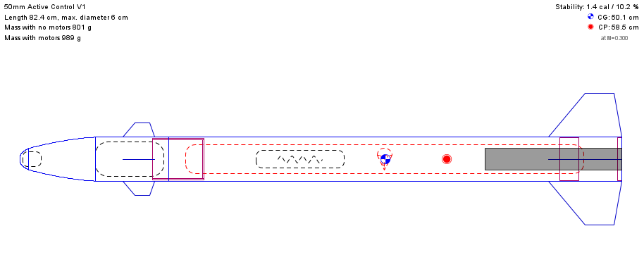
Custom STM32H743 flight computer and GNC software for a roll-rate-stabilised high-power rocket.



This is an engineering project, not a product. The safety case, regulatory compliance, and airworthiness of any vehicle built from this material are the builder's sole responsibility.
The project is designed to:
Control scope. The flight controller closes a loop on roll rate, not roll angle. It damps rate transients and cancels the standing roll moment produced by build asymmetry. It holds no commanded heading and has no outer attitude loop. Roll-angle hold and full three-axis attitude control are planned work and are not implemented.
This repository contains the hardware design, embedded software, simulation models, and analysis tools used during development.
| Parameter | Specification |
|---|---|
| Purpose | Active roll stabilisation for mid- and high-power rockets |
| Flight Computer | STM32H743 ARM Cortex-M7 |
| Control Surfaces | Four independently actuated canards |
| Control System | Proportional roll-rate damper, dynamic-pressure gain scheduled, with a slow bounded trim path for bias rejection |
| Control Scope | Roll rate damping and bias rejection. No attitude loop |
| Interfaces | I²C, UART and 6× PWM outputs |
| Data | On-board logging with optional telemetry |
| Simulation | MATLAB, Simulink, 6DOF modelling and Monte Carlo analysis |
| Architecture | Modular flight computer, sensor board and power distribution board |
| Design Goals | Low mass, modular, reliable and adaptable |
| License | Apache 2.0 |
| Feature | Status |
|---|---|
| Flight Computer Design | Complete |
| Flight Computer Testing | In Progress |
| Flight Software | In Progress |
| Flight Hardware Design | In Progress |
| Flight Hardware Testing | In Progress |
| Simulink Roll Model | Complete |
| Simulink 6DOF Model | Complete |
| MATLAB Monte Carlo Analysis | Complete |
| System Integration | Not Started |
| HITL Testing | Not Started |
| Flight Testing | Not Started |
Hyades-Flight-Computer
│
├── Documentation/
│   └── Images/
├── Firmware/
│   └── STM32IDE/
├── Hardware/
│   ├── 29mm Rocket/
│   ├── Avionics Bay/
│   ├── Canards/
│   ├── Fin Can/
│   └── PCB Designs/
└── Simulation/
    ├── Buck Regulator SPICE Simulation/
    ├── Canard Sizing/
    ├── HSE Clock SPICE Simulation/
└── Matlab Roll Tuning/The main PCB, containing all the computation and data gathering.
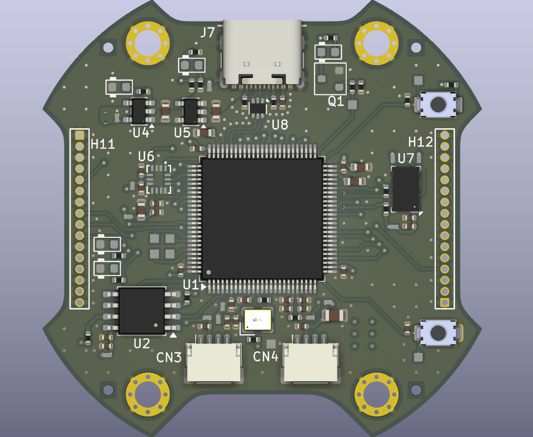
Rev 0.2 render; rev 0.3 layout in progress.
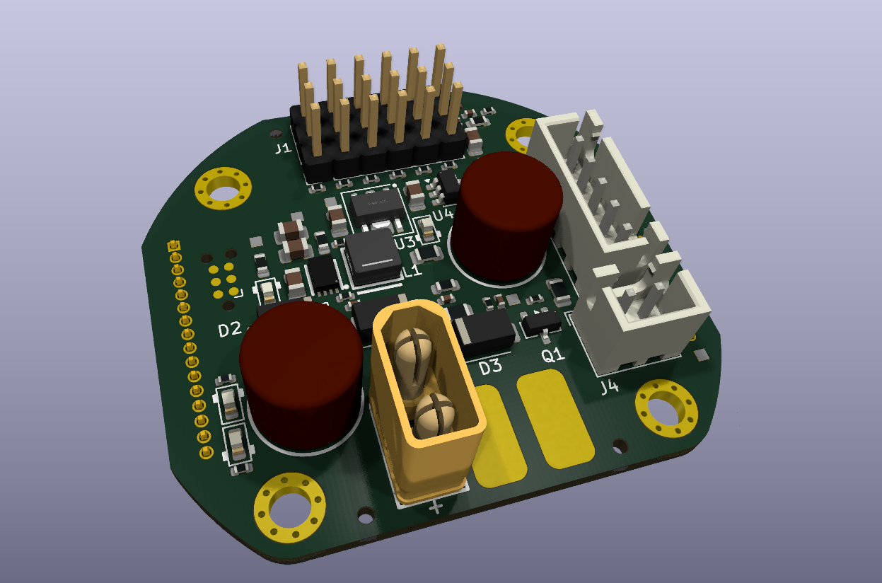
The PDB board, provides power and distributes PWM signals to the servos, as well as providing a clean 3V3 to the sensor board.
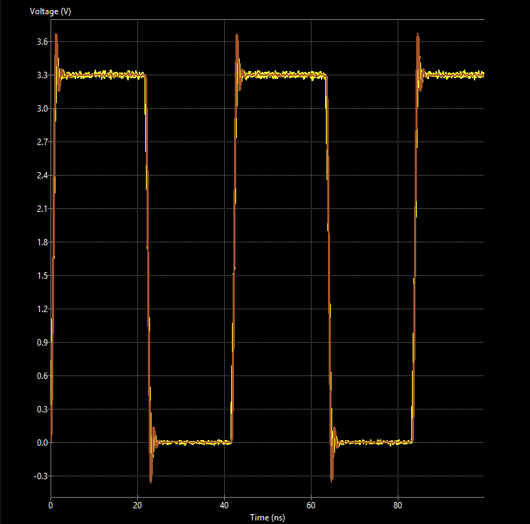
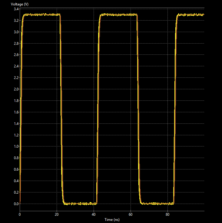
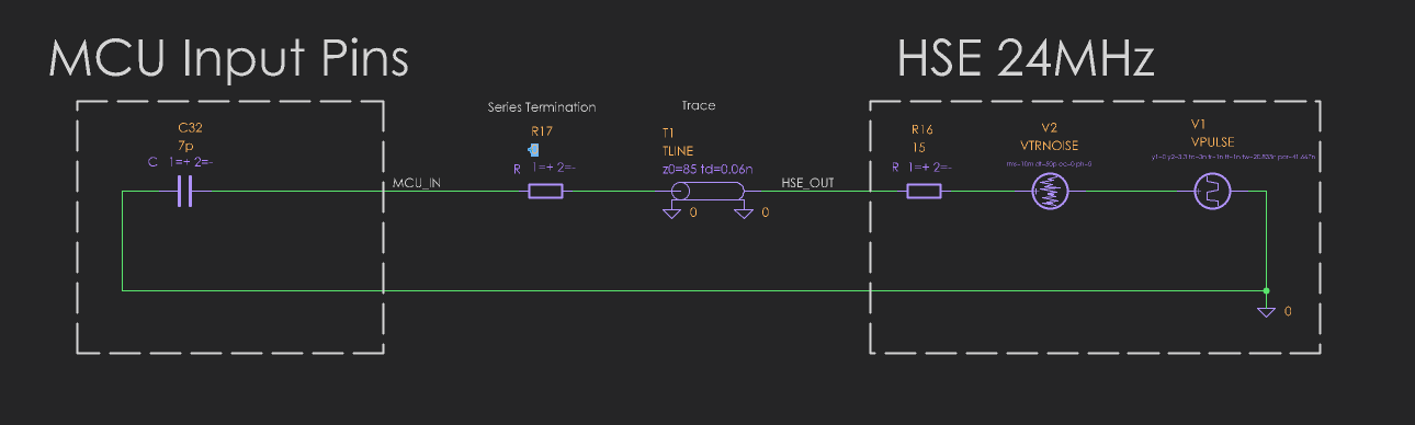
0 Ohm Series Termination vs 47 Ohm Series Termination for the 24 MHz HSE Oscillator, unnecessary? Yes, but a good opportunity to learn SPICE Simulations, plus it looks cool. Below the schematic that the simulations were derived from.
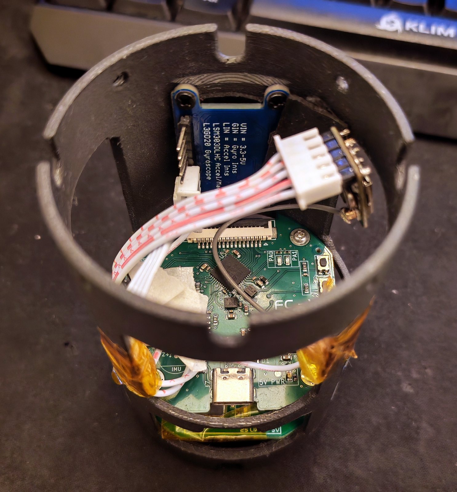
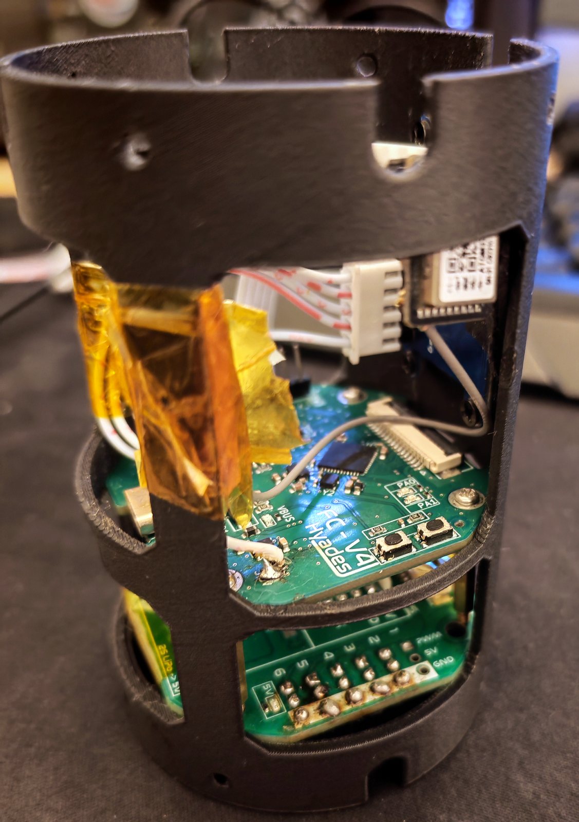
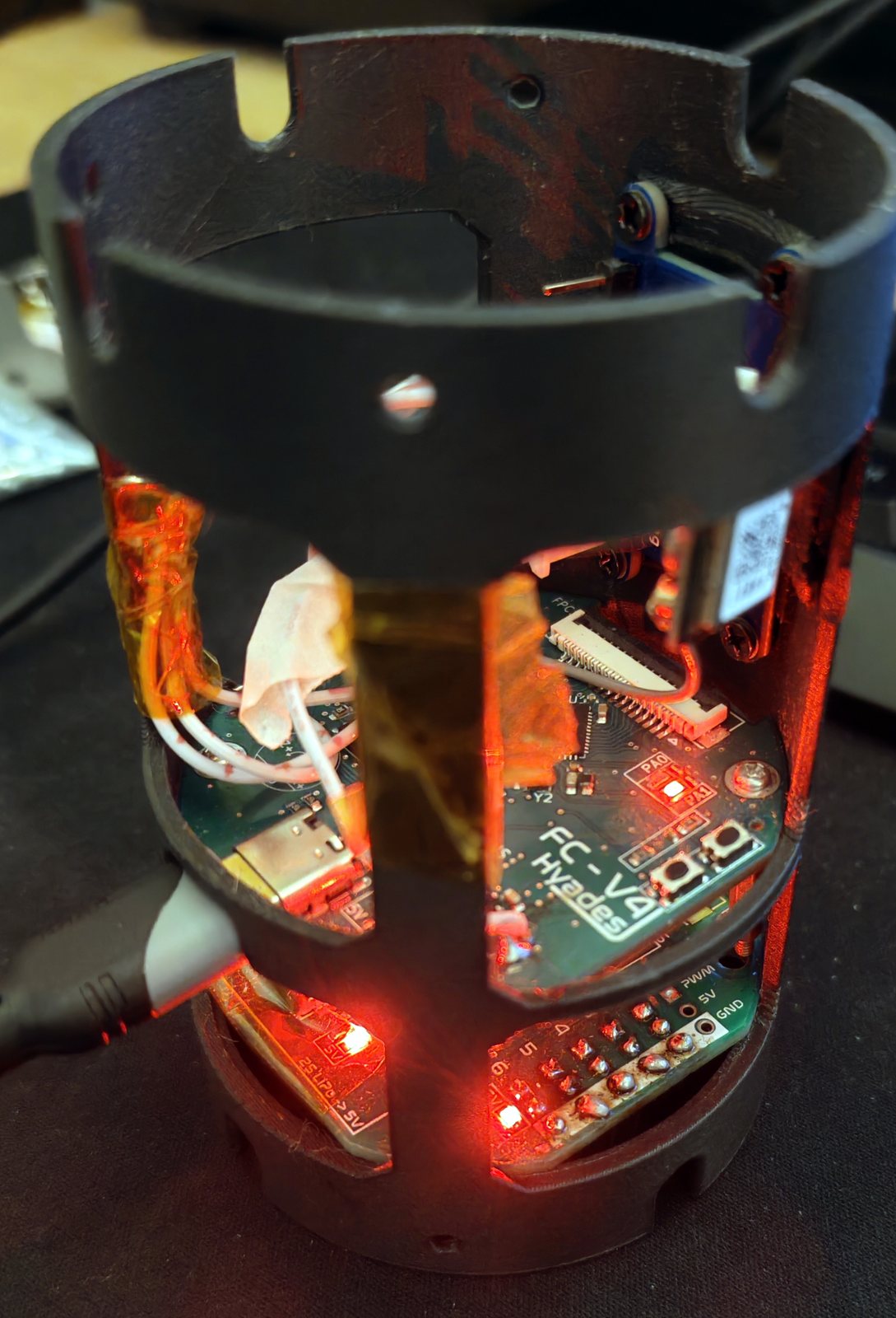
The second hardware iteration of the flight computer. The first failed due to many oversights and lack of basic knowledge. On this version, the MCU boots and runs, USB and PDB works completely. An incorrectly wired CS pin has caused a bus fault where the I2C bus thinks its SPI and so fails to communicate. Future redesign to address this and a number of other design/architecture level issues is in progress, enabled by kind sponsorship from JLCPCB. Also seen is the Sheppard PCB design for my research project, which served a dual purpose in allowing me to validate the layout and connections for all the critical components for the next iteration, such as the ICM-42688P IMU and STM32H743 MCU and controlled impedance USB-HS routing for high data rate logging.
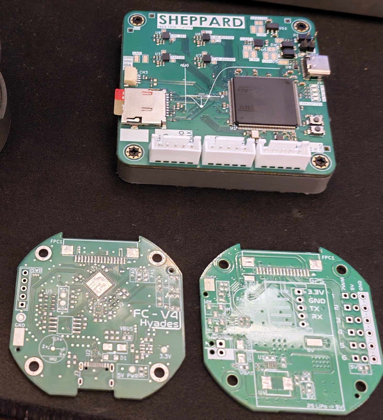
After some more testing, I have realised that the supposed ICM-42688-P's are actually QMI8658A IMU, substituted as a fake version of the target gyros (cross referenced WHO_AM_I 0x05, rev 0x7C, address 0x6B), after rewriting some of the code I got them working, allowing for a breakout board/bodge to be avoided. After collecting 2+ hours of data running at 16 g, 2048 dps, 224.2~ Hz ODR over I2C at 400kHz, I computed allan variance and then fitted a white-noise + Gauss-Markov + random-walk model to it (GMWM) with the rate-quantisation component computed separately under PQN model assumptions.
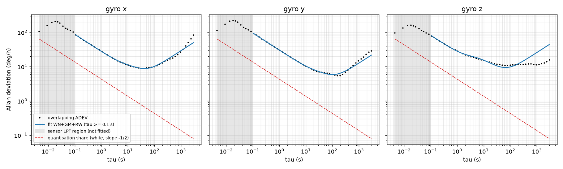
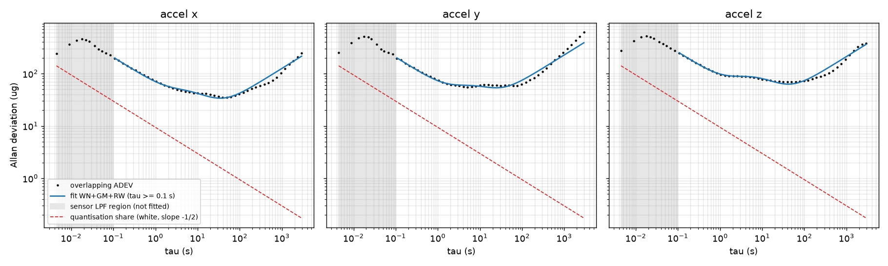
This is beneficial as the state estimator (IEKF) requires a model of the sensors noise to optimally estimate the current pose and to make its covariance trustworthy, which fault detection partly relies on. See Quantisation Research Project for my related work on this topic.
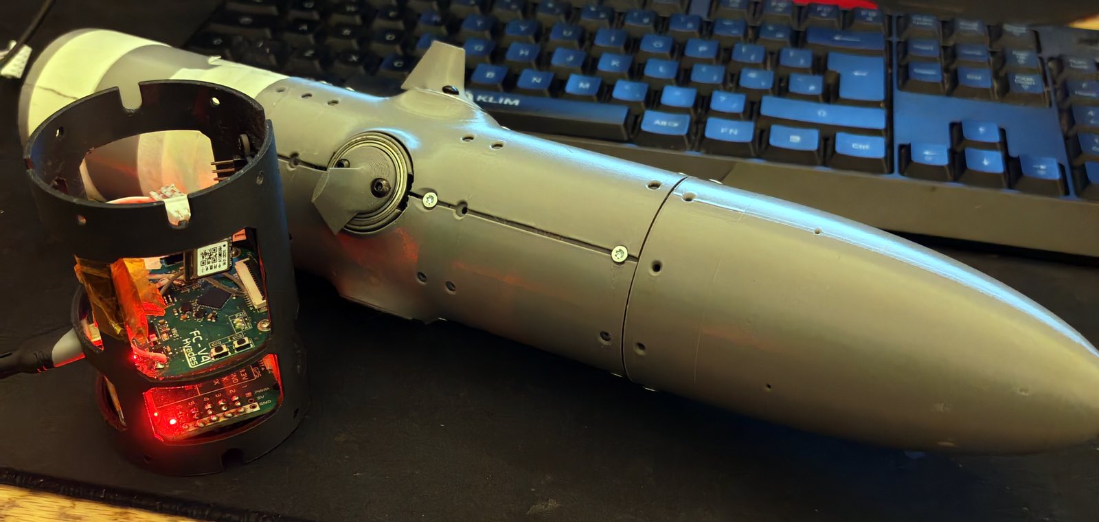
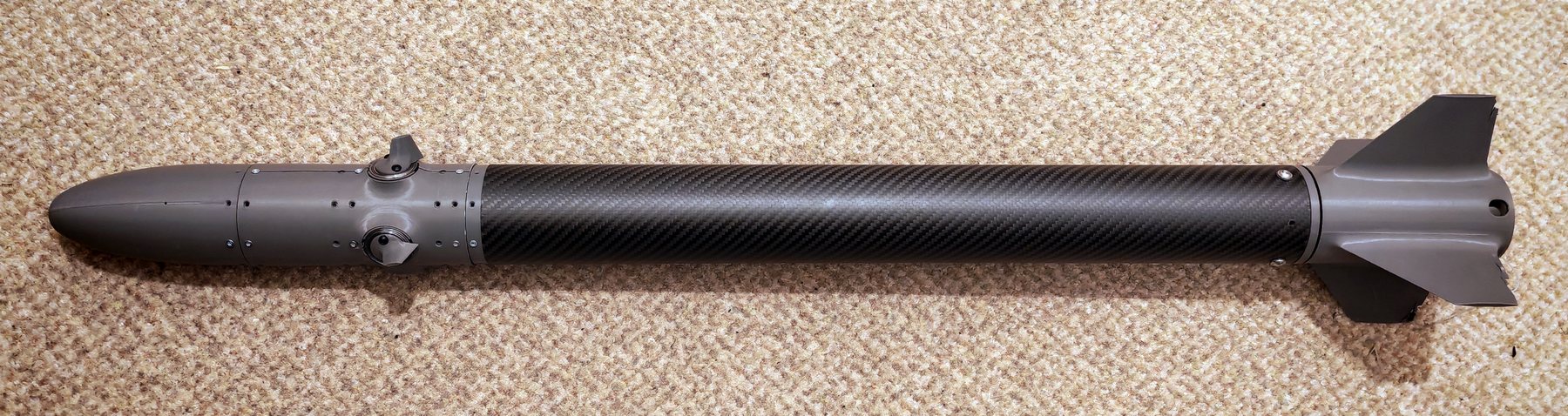
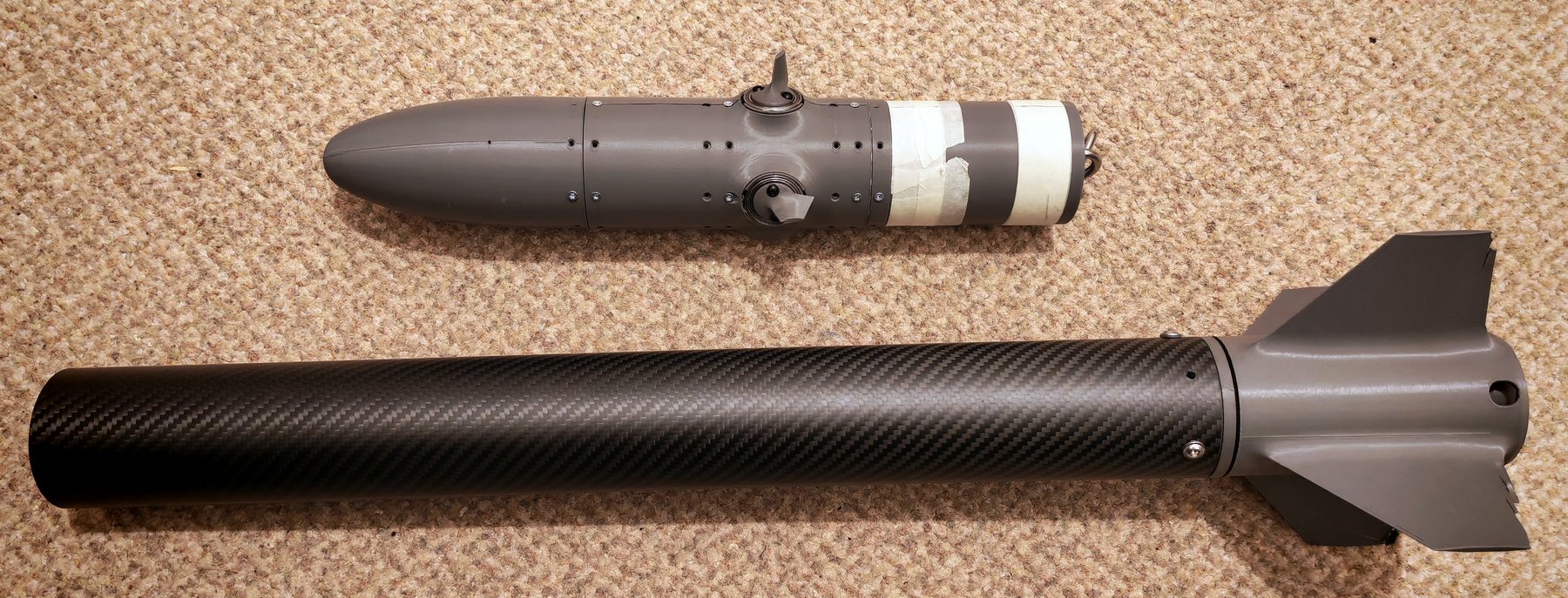
The built airframe, assembled and with the front avionics section separated from the booster.
CAD full assembly, an earlier render with the front section and nose cone missing.
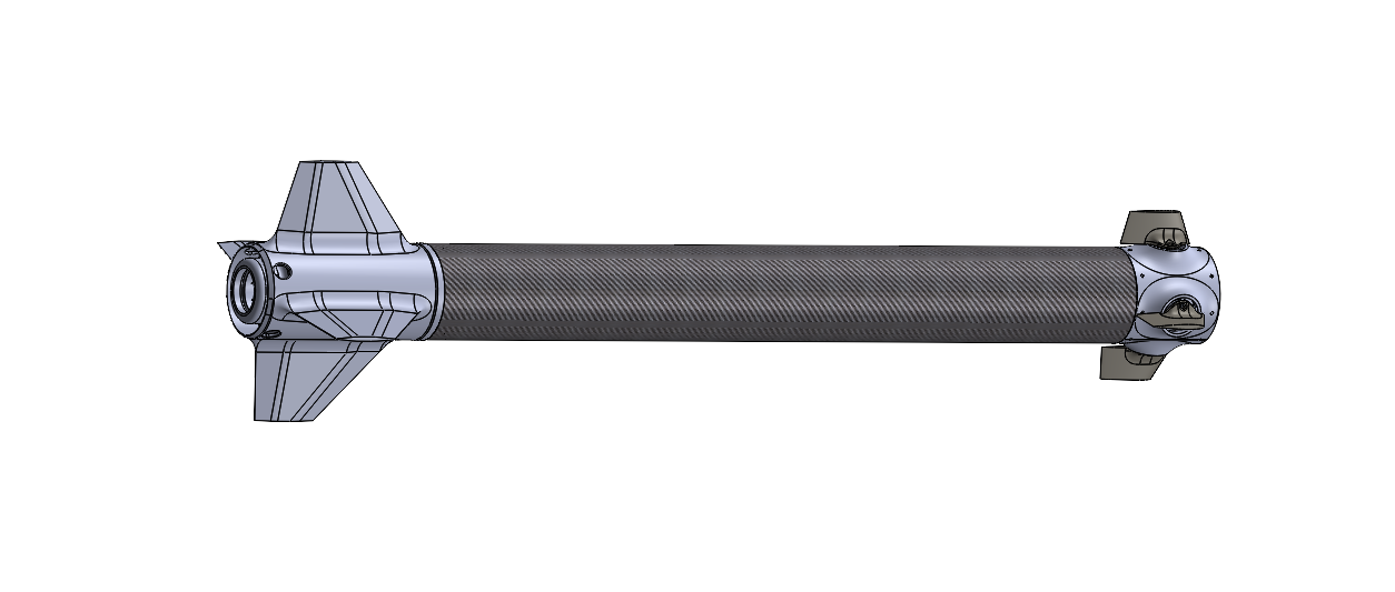
Spinning Rear Fin Can designed to avoid the roll reversal phenomenon where upstream control surfaces tip vortices interact with the downstream fixed fins, causing a difficult to predict moment in the opposite direction.
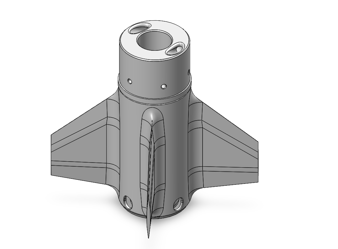
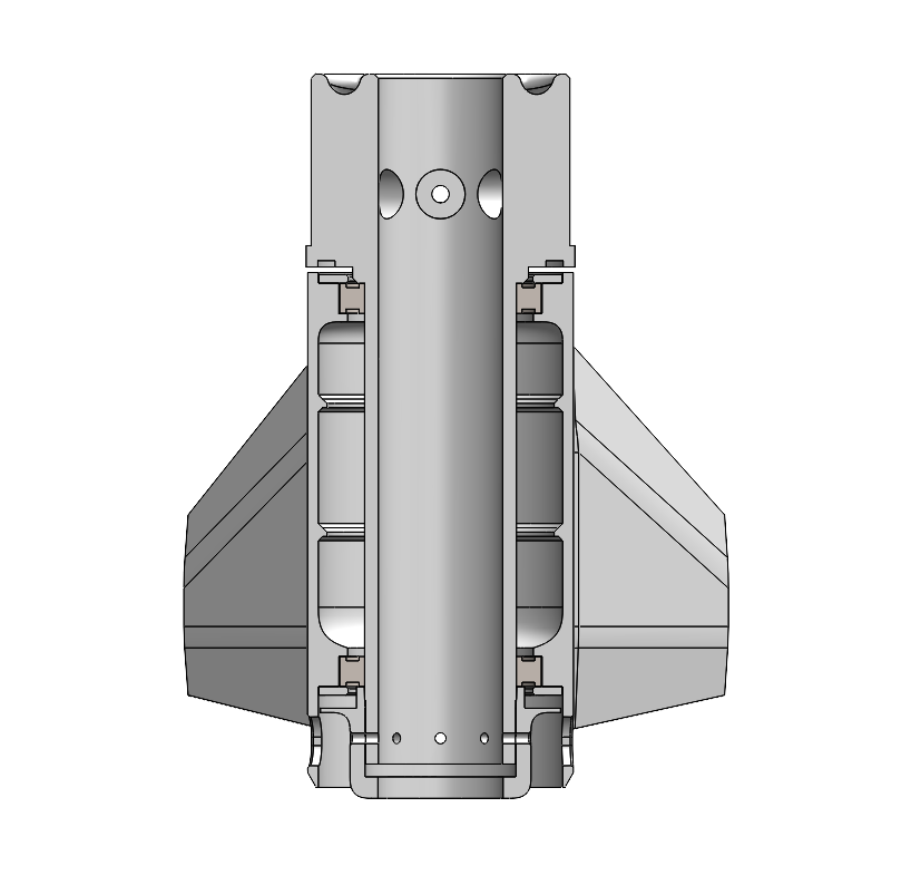
Front avionics assembly, WIP.
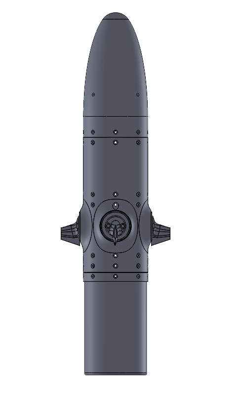
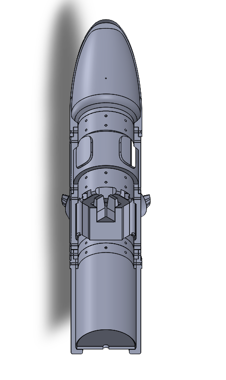
%words
%words
The loop closes on roll rate, along two paths.
Damping is proportional and gain scheduled on dynamic pressure, Kp = c / q_e. The 1/q schedule holds the open-loop crossover constant across the envelope.
Trim is a slow bounded integrator that cancels the standing roll moment Cl_0 from fin cant and build asymmetry. It is kept out of the damper because the deflection that cancels a standing bias, -Cl_0 / Cl_delta, is independent of q and V - one fixed deflection works everywhere, so it can be learned slowly and stay clear of the loop dynamics. Four gates bound it: bandwidth, a dead zone subtracted from the integrator input, a saturation freeze, and a clamp with a rate limit. It accepts an external Cl_0 estimate, so a future MEKF can supply the value directly.
Putting integral action in the damper instead produces a limit cycle against the servo dead zone. That dead zone sits inside the servo's own position loop, so command-side compensation does not reach it; dither on the command does. Flown at 1.5x the modelled dead zone, 125 Hz.
Open items. The trim saturation gate tests the pre-dither command while the travel clamp acts post-dither, so it can miss a saturation event within one dither amplitude of the stop. The dither frequency also needs checking against the servo's maximum frame rate.
%words
%words
400 dispersed runs per design point. Aerodynamic coefficients, vehicle properties, actuator parameters and the disturbance bias are sampled per run. The controller's dynamic-pressure estimate is drawn about the sampled truth rather than the nominal, so scheduling error compounds with aerodynamic dispersion instead of cancelling against it.
| Metric | Definition |
|---|---|
rms_err | RMS of (p - ref) over the steady tail |
bias | mean(p) - ref over the tail |
ripple_pp | max(p) - min(p) over the tail; limit-cycle amplitude |
activity | RMS surface rate; catches stick-slip |
growth | RMS of the last half of the tail over the first half; the stability test |
travel_peak / travel_steady | Travel used over the whole run / over the tail |
Dither amplitude was swept over four campaigns at matched dispersion. Limit-cycle amplitude falls sharply at the flown setting with no rise in surface activity; the cost shows up as a small steady rate bias.
c is set analytically from a 4 Hz crossover target; the numerical work confirms the margins near it survive parameter uncertainty rather than searching for an optimum. Margins come from the open-loop frequency response with the transport delay treated exactly, evaluated over paired (q, V) flight conditions spanning q = 2-40 kPa, with independent +/-30% on Cl_delta and Cl_p, accepted at phase margin >= 35 deg, gain margin >= 6 dB and peak sensitivity <= 2.0 at the worst corner. Constants are read from the parameter file rather than restated here.
A separate grid search over c and the trim parameters scores candidates on settling time, hang-off, limit-cycle amplitude and actuator demand, using the Monte Carlo campaign at each point.
Ti applies only to the legacy PI mode kept for A/B comparison.
%words
%words
%words
| Qty | Value | Footprint | References |
|---|---|---|---|
| 19 | TestPoint_Probe | PCM_4ms_TestPoint:TestPoint_Pad_04 | TP2, TP3, TP5, TP6, TP11, TP12, TP13, TP14, TP15, TP16, TP21, TP22, TP23, TP24, TP26, TP27 +3 |
| 16 | 100nF | PCM_JLCPCB:C_0402 | C1, C2, C3, C4, C5, C6, C7, C8, C9, C10, C15, C16, C21, C26, C28, C31 |
| 13 | NetTie | PCM_4ms_SolderJumper:JUMPER_SMD_1x2_tiny_shorted | TIE1, TIE3, TIE4, TIE5, TIE6, TIE7, TIE8, TIE9, TIE10, TIE11, TIE12, TIE13, TIE14 |
| 7 | 10kΩ | PCM_JLCPCB:R_0402 | R2, R5, R6, R7, R8, R9, R15 |
| 4 | 10nF | PCM_JLCPCB:C_0402 | C11, C14, C25, C29 |
| 4 | 330Ω | PCM_JLCPCB:R_0402 | R10, R16, R17, R20 |
| 4 | 4.7kΩ | PCM_JLCPCB:R_0402 | R18, R19, R22, R23 |
| 4 | TestPoint_Flag | PCM_4ms_TestPoint:TestPoint_Pad_04 | TP1, TP4, TP17, TP18 |
| 4 | ~ | PCM_JLCPCB:Hole, 3mm | H1, H2, H3, H4 |
| 4 | ~ | PCM_JLCPCB:Hole_Tooling_JLCPCB | H5, H6, H7, H10 |
| 3 | 2.2uF | PCM_JLCPCB:C_0603 | C12, C13, C24 |
| 3 | TestPoint_Flag | Connector_Wire:SolderWirePad_1x01_SMD_2x4mm | TP19, TP20, TP25 |
| 2 | 10uF | PCM_JLCPCB:C_0805 | C27, C33 |
| 2 | 10uF | PCM_JLCPCB:C_0402 | C30, C32 |
| 2 | 1uF | PCM_JLCPCB:C_0402 | C22, C23 |
| 2 | 33Ω | PCM_JLCPCB:R_0402 | R4, R21 |
| 2 | 5.1kΩ | PCM_JLCPCB:R_0402 | R11, R12 |
| 2 | KH-1_27FH-1X16P-H4_3 | JLCImport:KH-1_27FH-1X16P-H4_3 | U5, U9 |
| 2 | LED_0603_Red | PCM_LED_SMD_AKL:LED_0603_1608Metric | LED2, LED5 |
| 2 | SM04B-SRSS-TB_LF_SN | Connector_JST:JST_SH_SM04B-SRSS-TB_1x04-1MP_P1.00mm_Horizontal | CN3, CN4 |
| 2 | Tactile Button, 160gf | PCM_JLCPCB:SW_TS-1088-AR02016 | S1, S2 |
| 1 | 100kΩ | PCM_JLCPCB:R_0402 | R14 |
| 1 | 1kΩ | PCM_JLCPCB:R_0402 | R3 |
| 1 | 33kΩ | PCM_JLCPCB:R_0402 | R13 |
| 1 | 4.7uF | PCM_JLCPCB:C_0603 | C19 |
| 1 | AP2115R5-3.3TRG1 | PCM_Package_TO_SOT_SMD_AKL:Diodes_SOT-89-5 | U3 |
| 1 | ASDM1-24_000MHZ-LC-T | PCM_JLCPCB:OSC-SMD_4P-L3.2-W2.5-BL | X1 |
| 1 | ICM-42688-P | JLCImport:ICM-42688-P | U6 |
| 1 | KH-TYPE-C-16P | Connector_USB:USB_C_Receptacle_GCT_USB4105-xx-A_16P_TopMnt_Horizontal | J7 |
| 1 | LED_0603_Green | PCM_LED_SMD_AKL:LED_0603_1608Metric | LED1 |
| 1 | LED_0603_Orange | PCM_LED_SMD_AKL:LED_0603_1608Metric | LED6 |
| 1 | MAX40200AUK | Package_TO_SOT_SMD:SOT-23-5 | U4 |
| 1 | MMBT3904 | PCM_Package_TO_SOT_SMD_AKL:SOT-23 | Q1 |
| 1 | MS5611-01BA03-50 | Package_LGA:LGA-8_3x5mm_P1.25mm | U7 |
| 1 | STM32H743VIT6 | Package_QFP:LQFP-100_14x14mm_P0.5mm | U1 |
| 1 | TC2030 | Connector:Tag-Connect_TC2030-IDC-NL_2x03_P1.27mm_Vertical | J5 |
| 1 | USBLC6-2P6 | Package_TO_SOT_SMD:SOT-666 | U8 |
| 1 | W25Q128JVS | Package_SO:SOIC-8_5.3x5.3mm_P1.27mm | U2 |
thejamesrhodes/Hyades-Flight-Computer
Full Hardware and Electronics design, Bare-metal GNC flight software for an actively attitude-controlled high-power rocket

thejamesrhodes/Hyades-Flight-Computer
Full Hardware and Electronics design, Bare-metal GNC flight software for an actively attitude-controlled high-power rocket

thejamesrhodes/Hyades-Flight-Computer
Full Hardware and Electronics design, Bare-metal GNC flight software for an actively attitude-controlled high-power rocket

thejamesrhodes/Hyades-Flight-Computer
Full Hardware and Electronics design, Bare-metal GNC flight software for an actively attitude-controlled high-power rocket

thejamesrhodes/Hyades-Flight-Computer
Full Hardware and Electronics design, Bare-metal GNC flight software for an actively attitude-controlled high-power rocket

thejamesrhodes/IMU-Quantisation-research-project
Research into quantisation effects in MEMS gyroscopes using custom STM32 hardware.


jayis1/hardware-design-lab
Full-cycle hardware device designs — each device in its own subfolder with architecture, schematics, PCB layout, and software stack

vroland/epdiy-hardware
Hardware design files for EPDiy: https://github.com/vroland/epdiy.

martinberlin/Sharp-LV
This KiCad board aims to be a low consumption driver for SHARP LCDs w/optional touch. MCU: Nordic RF52 (not tested) | ESP32S3 buy one in Tindie before sending to production

Def12345678/M-FC-G474-Rev-A
Modular STM32G474 Flight Controller Rev-A. Focus on modularity using JST-SH connectors for all peripherals (ESC, RX, etc.). ICM-42688-P IMU and DPS368 barometer. Requires external 5V 2.5A (no onboard BEC).

Ekta-Gupta27/custom-flight-controller-pcb
Custom flight controller PCB designed in KiCad with STM32F7, multiple sensors, CAN, USB, telemetry, PWM and IO interfaces.

mrcha033/hw-codesign
Agentic hardware co-design: brief to KiCad, firmware, 3D review, and explicit fabrication blockers.
It measures 45.2 × 41.2 mm and has 4 copper layers, 1.6 mm thick.
120 parts, built around the STM32H743VIT6, W25Q128JVSIQ, AP2115R5-3.3TRG1 and ICM-42688-P. The full list of its parts is on this page, with links to each part's symbol and footprint where PCBKit's library has them.
From the thejamesrhodes/Hyades-Flight-Computer repository on GitHub, at the commit this page was made from: the board is Hardware/PCB Designs/MCU Board 0.3/MCU Board 0.3/MCU Board 0.3.kicad_pcb and its schematic Hardware/PCB Designs/MCU Board 0.1/MCU Board 0.1.kicad_sch. PCBKit opens the board in the browser, with nothing to install.
Its repository publishes it under the Apache-2.0 licence: you may reuse it on that licence's terms (keep the author's notice, and for a copyleft licence share your changes alike).