2 layers100 × 100 mm
Adder
tensorway/2000transistors
The project is made in Kicad. If you want to learn more about it visit howcpuworks.com.
208 parts

 tensorway/2000transistors
The project is made in Kicad. If you want to learn more about it visit howcpuworks.com.
Clock board is an open-source printed circuit board by tensorway, from the tensorway/2000transistors repository on GitHub. It is a 2-layer board of 100 × 100 mm with 109 parts on 60 nets, routed with 901 tracks and 6 vias.
Its parts include 45 resistors, 40 transistors, 12 connectors, 6 capacitors and 2 ICs. It belongs with the lEDs and displays boards of this library.
The project is made in Kicad. If you want to learn more about it visit howcpuworks.com.
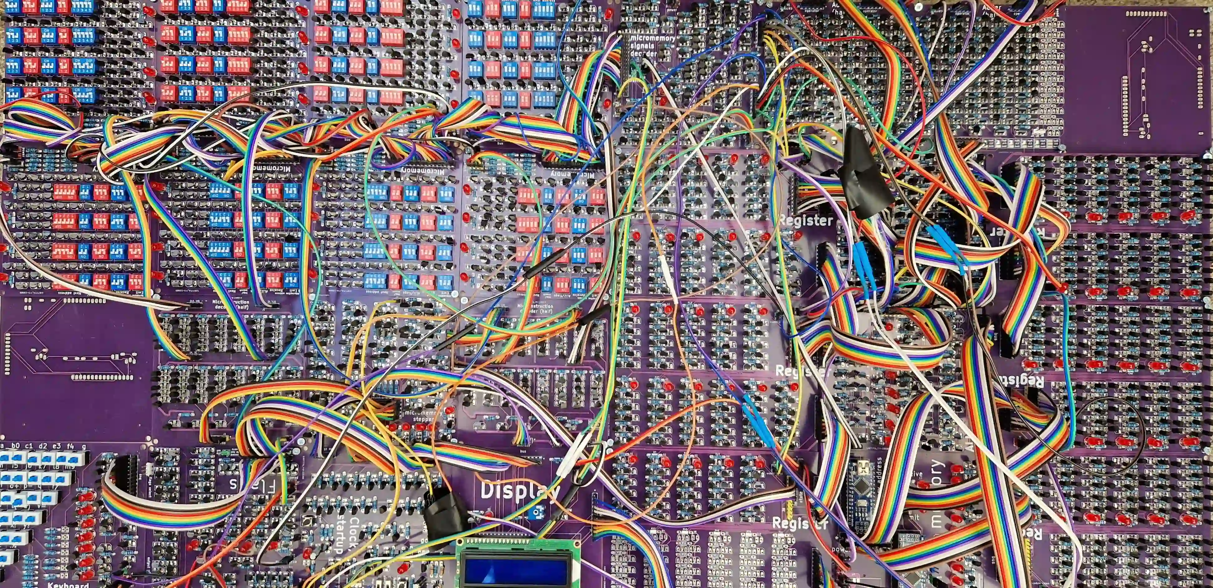
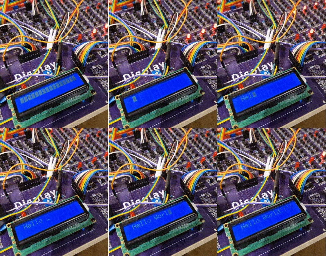
While I could fix the bugs I do not want to check is everything working again because I would need to solder things again. This is why I list them, so you can either fix them yourselves before or after soldering (I did after). Some bugs are just layout bugs, which means you need to be aware of them but not necessarily fix them.
Micromemory:
Micromemory stepper:
Keyboard
Flags
Clock
ALU
| Qty | Value | Footprint | References |
|---|---|---|---|
| 43 | R | processor2:resistor_tight | R1, R2, R10, R11, R12, R13, R14, R15, R16, R17, R18, R19, R20, R21, R22, R23 +27 |
| 36 | 2N7000 | processor2:2n7000_tight | Q1, Q2, Q10, Q11, Q12, Q13, Q14, Q15, Q16, Q17, Q18, Q19, Q20, Q21, Q22, Q23 +20 |
| 4 | 2N2219 | processor2:bjt | Q3, Q4, Q5, Q6 |
| 4 | CP | processor2:capacitor | C1, C2, C3, C4 |
| 3 | Conn_01x02_Male | processor2:2pin_tight | J3, J4, J12 |
| 2 | C | processor2:capacitor | C5, C6 |
| 2 | Conn_01x01_Male | processor2:1pin | J1, J2 |
| 2 | Conn_01x05_Male | processor2:5pin_tight | J7, J11 |
| 2 | Conn_01x11_Male | processor2:11pin_tight | J5, J6 |
| 2 | LED | processor2:led_5mm_tight | D1, D2 |
| 2 | R | processor2:resistor_led_tight | R3, R4 |
| 2 | SW_Push_Dual | processor2:push_button | SW1, SW2 |
| 2 | alu_sel | processor2:3pin_tight | J8, J9 |
| 2 | slide_switch | processor2:slide_switch | U1, U2 |
| 1 | flags_enable_out | processor2:1pin | J10 |
It measures 100 × 100 mm and has 2 copper layers, 1.6 mm thick.
109 parts. The full list of its parts is on this page, with links to each part's symbol and footprint where PCBKit's library has them.
From the tensorway/2000transistors repository on GitHub, at the commit this page was made from: the board is src/clock_board.kicad_pcb. PCBKit opens the board in the browser, with nothing to install.
Its repository states no licence, so its author keeps all rights: ask tensorway before reusing the design.
tensorway/2000transistors
The project is made in Kicad. If you want to learn more about it visit howcpuworks.com.

tensorway/2000transistors
The project is made in Kicad. If you want to learn more about it visit howcpuworks.com.

tensorway/2000transistors
The project is made in Kicad. If you want to learn more about it visit howcpuworks.com.

tensorway/2000transistors
The project is made in Kicad. If you want to learn more about it visit howcpuworks.com.

tensorway/2000transistors
The project is made in Kicad. If you want to learn more about it visit howcpuworks.com.

tensorway/2000transistors
The project is made in Kicad. If you want to learn more about it visit howcpuworks.com.

tensorway/2000transistors
The project is made in Kicad. If you want to learn more about it visit howcpuworks.com.

tensorway/2000transistors
The project is made in Kicad. If you want to learn more about it visit howcpuworks.com.

tensorway/2000transistors
The project is made in Kicad. If you want to learn more about it visit howcpuworks.com.

tensorway/2000transistors
The project is made in Kicad. If you want to learn more about it visit howcpuworks.com.

tensorway/2000transistors
The project is made in Kicad. If you want to learn more about it visit howcpuworks.com.

tensorway/2000transistors
The project is made in Kicad. If you want to learn more about it visit howcpuworks.com.

pierrechevalier83/ferris
A low profile split keyboard designed to satisfy one single use case elegantly

joshajohnson/Hub16
A macro pad with 16 keys, two rotary encoders, a four port USB hub, and plenty of LEDs!

slu4coder/Minimal-UART-Computer-1-2
Legacy: Version 1 and 2 of my TTL-only CPU featuring UART I/O, an expansion port, 512KB SSD at up to 10MHz clock speed


BerkeleyHCI/PolymorphicBlocks
A Python-based hardware description language for PCBs for higher-level (block-diagram / system-architecture level) PCB design through libraries of directly reusable subcircuit generators.


