Skip to the content
PCBKitNew board
2 layers100 × 100 mmPc step board, the printed circuit board in 3D

The project is made in Kicad. If you want to learn more about it visit howcpuworks.com.

Size
100 × 100 mm
Copper layers
2
Thickness
1.6 mm
Parts
185
Nets
122
Pads
489
Tracks, vias
1,942, 14
Routed
Yes
KiCad
KiCad 5 (file 20171130)
Created
25 Oct 2023
Updated
25 Oct 2023

Overview

Pc step board is an open-source printed circuit board by tensorway, from the tensorway/2000transistors repository on GitHub. It is a 2-layer board of 100 × 100 mm with 185 parts on 122 nets, routed with 1,942 tracks and 14 vias.

Its parts include 102 transistors, 62 resistors, 6 diodes, 5 capacitors and 1 connector.

README

README.md

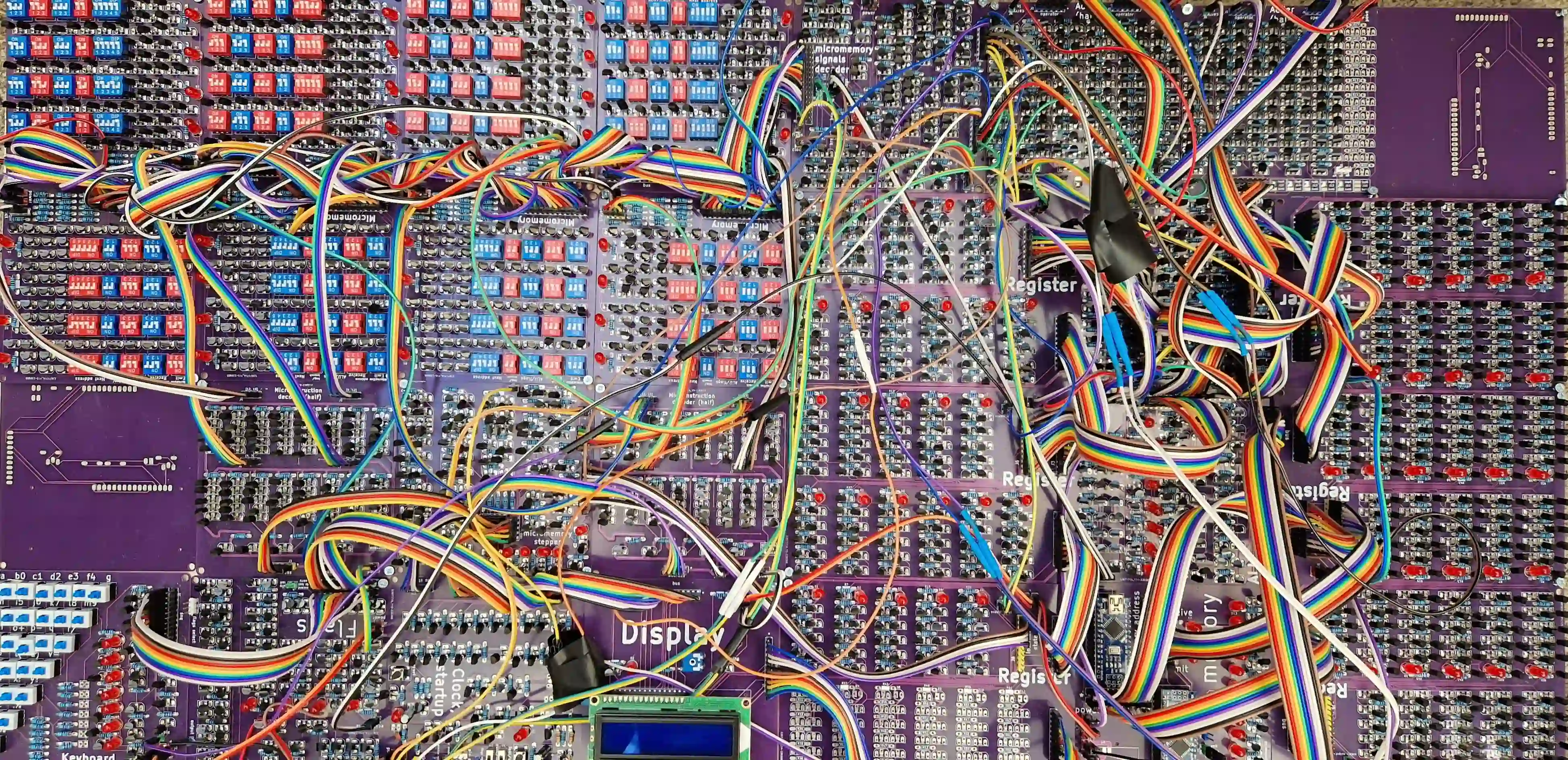
2000 MOSFET processor

The project is made in Kicad. If you want to learn more about it visit howcpuworks.com.

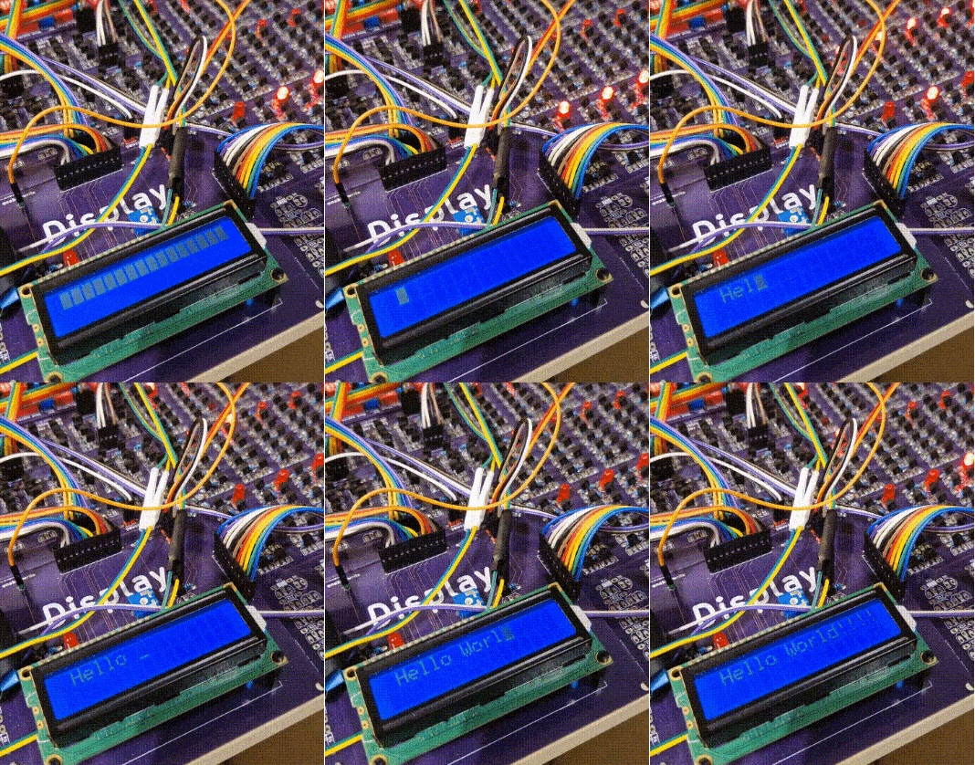
Full cpu Hello world

Conventions

  • all transistors on a board point into the same direction (or 2 perpendicular ones if needed)
  • all leds point into the same direction
  • 1k resistors are labeled with white rectangle, 1M with empty one (only violation is in the Clock board and two voltage divider resistors in LCD board)
  • "*" means high significance bits
  • "+" means positive 5V

Tips

  • you dont need to use extra usb for the power, powering through arduino is enough
  • Adder is made out of 2 smaller 6 bit adders, this means that you do not have to solder one bit (6+6=12 != 11)
  • instruction register needs only 5bits which means you do not have to solder upper 6 bits (all registers are the same board to lower costs)
  • when soldering
    • first put resistors
    • than transistors from the top left (top right if left handed)
    • leds and pin headers last

Important

  • to lower costs all registers have the same board, but TMP and IR registers do not have input and output connected to the bus, this means you have to connect it on other registers
  • You need to find the voltage that works for your LCD contrast and put those resistors

Components

  • 2N7000 MOSFETs
  • BC547 (BJT) only 4 for the astable
  • 1000 ohm registers for leds
  • 1M ohm for logic

Bugs

While I could fix the bugs I do not want to check is everything working again because I would need to solder things again. This is why I list them, so you can either fix them yourselves before or after soldering (I did after). Some bugs are just layout bugs, which means you need to be aware of them but not necessarily fix them.

Micromemory:

  • shuffled by row led, select and switches - layout bug
  • 0th line not connected to rest

Micromemory stepper:

  • shuffeled LED state order - layout bug
  • add delay from clock to it (for example RC)

Keyboard

  • same signals for simetrical (with respect to keyboard diagonal) switches
    • effectively half the number of switches
  • 1 bit not connected

Flags

  • second to last carry and last carry labels mixed - layout bug
  • flags selector selects 0 always

Clock

  • manual clock does not have a debouncer

ALU

  • add OR between ALU decoded ops and give Adder the output

Parts

185
QtyValueFootprintReferences
1022N7000processor2:2n7000_tightQ1, Q2, Q10, Q11, Q12, Q13, Q14, Q15, Q16, Q17, Q18, Q19, Q20, Q100, Q101, Q102 +86
56Rprocessor2:resistor_tightR1, R2, R10, R11, R12, R13, R14, R15, R16, R17, R18, R19, R20, R22, R28, R29 +40
6LEDprocessor2:led_5mm_tightD1, D2, D3, D4, D5, D6
6Rprocessor2:resistor_led_tightR21, R23, R24, R25, R26, R27
5Cprocessor2:capacitorC1, C2, C3, C4, C5
4Conn_01x05_Maleprocessor2:5pin_tightfrom instruction, from_umemory, J9, next uinstruction
2Conn_01x02_Maleprocessor2:2pin_tightpower, power
1Conn_01x01_Maleprocessor2:1pinhop
1clckprocessor2:2pin_tightJ5
1zero_start_inprocessor2:5pin_tightzero
1zero_start_outprocessor2:5pin_tightzero

Questions

How big is the Pc step board PCB?

It measures 100 × 100 mm and has 2 copper layers, 1.6 mm thick.

What parts does the Pc step board use?

185 parts. The full list of its parts is on this page, with links to each part's symbol and footprint where PCBKit's library has them.

Where can I download the Pc step board KiCad files?

From the tensorway/2000transistors repository on GitHub, at the commit this page was made from: the board is src/pc_step_board.kicad_pcb. PCBKit opens the board in the browser, with nothing to install.

Can I use the Pc step board design in my own project?

Its repository states no licence, so its author keeps all rights: ask tensorway before reusing the design.

More from tensorway/2000transistors

12
  • 2 layers100 × 100 mmAdder, the printed circuit board in 3D

    Adder

    tensorway/2000transistors

    The project is made in Kicad. If you want to learn more about it visit howcpuworks.com.

    208 parts
  • 2 layers150 × 100 mmRegister, the printed circuit board in 3D

    Register

    tensorway/2000transistors

    The project is made in Kicad. If you want to learn more about it visit howcpuworks.com.
    206 parts
  • 2 layers100 × 100 mmAdd select board, the printed circuit board in 3D

    Add select board

    tensorway/2000transistors

    The project is made in Kicad. If you want to learn more about it visit howcpuworks.com.
    203 parts
  • 2 layers100 × 100 mmUmem distribution, the printed circuit board in 3D

    Umem distribution

    tensorway/2000transistors

    The project is made in Kicad. If you want to learn more about it visit howcpuworks.com.

    168 parts
  • 2 layers100 × 100 mmFlags board, the printed circuit board in 3D

    Flags board

    tensorway/2000transistors

    The project is made in Kicad. If you want to learn more about it visit howcpuworks.com.

    158 parts
  • 2 layers100 × 100 mmAlu, the printed circuit board in 3D

    Alu

    tensorway/2000transistors

    The project is made in Kicad. If you want to learn more about it visit howcpuworks.com.

    157 parts
  • 2 layers100 × 100 mm4 lines umemory, the printed circuit board in 3D

    4 lines umemory

    tensorway/2000transistors

    The project is made in Kicad. If you want to learn more about it visit howcpuworks.com.

    117 parts
  • 2 layers100 × 100 mm5decoder32 half, the printed circuit board in 3D

    5decoder32 half

    tensorway/2000transistors

    The project is made in Kicad. If you want to learn more about it visit howcpuworks.com.

    114 parts
  • 2 layers100 × 100 mmClock board, the printed circuit board in 3D

    Clock board

    tensorway/2000transistors

    The project is made in Kicad. If you want to learn more about it visit howcpuworks.com.

    109 parts
  • 2 layers100 × 100 mmKeyboard, the printed circuit board in 3D

    Keyboard

    tensorway/2000transistors

    The project is made in Kicad. If you want to learn more about it visit howcpuworks.com.

    103 parts
  • 2 layers100 × 100 mmMemory board, the printed circuit board in 3D

    Memory board

    tensorway/2000transistors

    The project is made in Kicad. If you want to learn more about it visit howcpuworks.com.

    53 parts
  • 2 layers100 × 100 mmLcd board, the printed circuit board in 3D

    Lcd board

    tensorway/2000transistors

    The project is made in Kicad. If you want to learn more about it visit howcpuworks.com.

    14 parts

Similar boards

  • 2 layers99.1 × 99.1 mmPower supply, the printed circuit board in 3D

    Power supply

    thebiguno/microcontroller-projects

    A home for a bunch of microcontroller projects which don't warrant their own repos.

    185 parts75
  • 2 layers289.9 × 99.4 mmDecent800-M, the printed circuit board in 3D

    Decent800-M

    bleroy/3d-junkyard

    Random 3D models

    185 parts69
  • 2 layers100 × 93 mmSpeeduino base, the printed circuit board in 3D

    Speeduino base

    Tjeerdie/SPECTRE

    Speeduino compatible engine control unit (ECU) based around black STM32F407VET6 board.

    185 parts59GPL-3.0
  • 2 layers140.7 × 86.5 mmUPD board, the printed circuit board in 3D

    UPD board

    uniclogs/uniclogs-hardware

    University Class Open Ground Station Hardware

    185 parts32GPL-3.0
  • 2 layers29.5 × 108.6 mmMiniDJ Back, the printed circuit board in 3D

    MiniDJ Back

    Thorinair/Avalon-Harmonics

    A collection of Avalon Harmonics branded synthesizer modules.

    185 parts26CC-BY-SA-4.0
  • 2 layers76 × 46 mmKampela D1, the printed circuit board in 3D

    Kampela D1

    Alzymologist/Kampela

    Hardware signer and key storage for Substrate ecosystem

    185 parts21GPL-3.0
  • 2 layers100 × 110 mmCz badge hardware, the printed circuit board in 3D

    Cz badge hardware

    hackzone/cz20-badge

    Node.js build static site for using with Hatchery over WebUSB

    185 parts13
  • 2 layers210.4 × 161.9 mmT80-5000-right, the printed circuit board in 3D

    T80-5000-right

    nearestexit/t80-5000

    QMK Compatible RP2040-based USB PCBs for the Cherry G80-5000 and the G80-5700.

    185 parts6