
4 layers62.1 × 83.8 mm
Ss main board
loopj/short-stack
World's Smallest Nintendo Wii, using a trimmed motherboard and custom stacked PCBs
69 parts804

 sunpazed/attiny16-breakout2
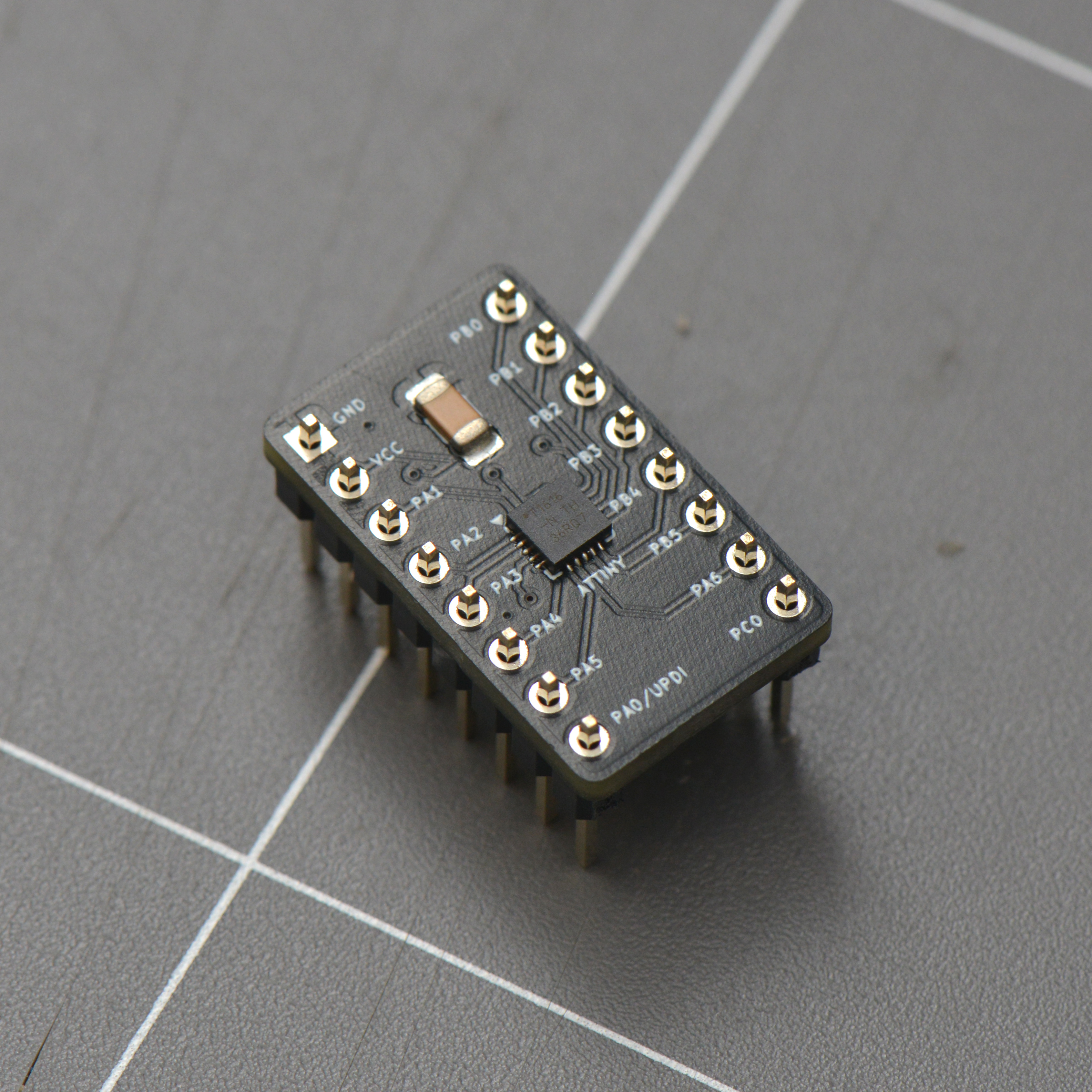
To keep things small (DIP-16), only a subset of pins are avalable — Port A pins (PA0-PA6) and Port B pins (PB0-PB5), along with a single PC0 pin;
Attiny16-breakout is an open-source printed circuit board by sunpazed, from the sunpazed/attiny16-breakout repository on GitHub, published under the GPL-3.0 licence. It is a 2-layer board of 13.1 × 21.7 mm with 3 parts on 20 nets, routed with 73 tracks and 6 vias.
It is built around the ATTINY1616-MN. Its parts include 1 capacitor and 1 connector. It belongs with the interfaces and adapters boards and the AVR (ATmega, ATtiny) boards of this library.
To keep things small (DIP-16), only a subset of pins are avalable — Port A pins (PA0-PA6) and Port B pins (PB0-PB5), along with a single PC0 pin;
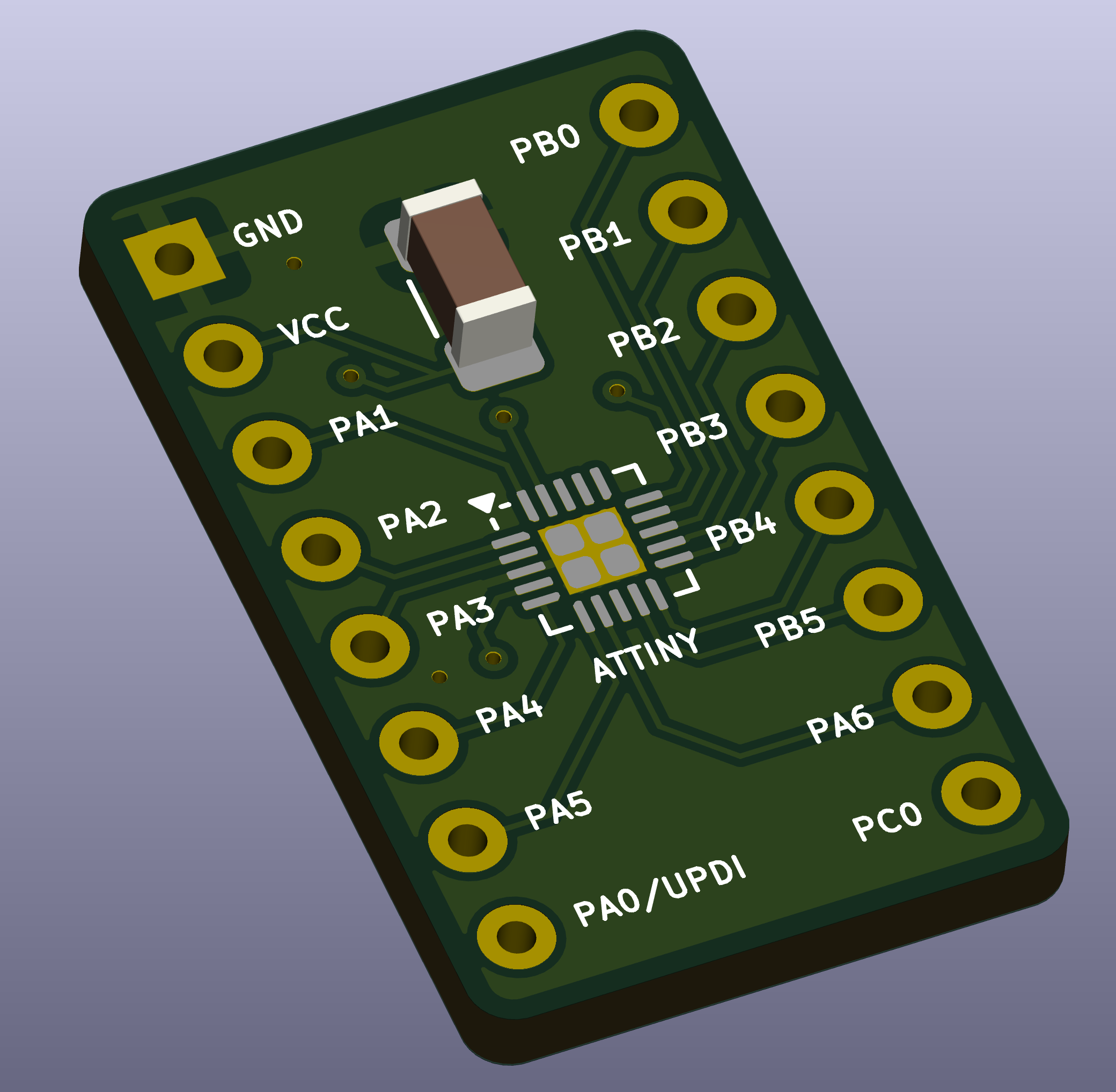
A small 0.1uF decoupling capacitor is also included to simplify usage on the breadboard.
| Qty | Value | Footprint | References |
|---|---|---|---|
| 1 | ATtiny1616-M | Package_DFN_QFN:VQFN-20-1EP_3x3mm_P0.4mm_EP1.7x1.7mm | ATTINY |
| 1 | C | Capacitor_SMD:C_1206_3216Metric_Pad1.33x1.80mm_HandSolder | C1 |
| 1 | Conn_02x08_Counter_Clockwise | Package_DIP:DIP-16_W10.16mm | J1 |
It measures 13.1 × 21.7 mm and has 2 copper layers, 1.6 mm thick.
3 parts, built around the ATTINY1616-MN. The full list of its parts is on this page, with links to each part's symbol and footprint where PCBKit's library has them.
From the sunpazed/attiny16-breakout repository on GitHub, at the commit this page was made from: the board is attiny16-breakout.kicad_pcb and its schematic attiny16-breakout.kicad_sch. PCBKit opens the board in the browser, with nothing to install.
Its repository publishes it under the GPL-3.0 licence: you may reuse it on that licence's terms (keep the author's notice, and for a copyleft licence share your changes alike).
loopj/short-stack
World's Smallest Nintendo Wii, using a trimmed motherboard and custom stacked PCBs


kieraneglin/hexagon-art
A passive breakout board: two lever-terminal inputs, three JST XH outputs, all six conductors (RX bus, two spares, +12V, GND, +5V) paralleled straight across. No active components, no regulation, nothing to configure.

engineerbo/flashlight-dev-hw
This repository contains design files for the development board for a flashlight boost driver. The test firmware can be found in the firmware repository.

hojadurdy/Flux_Capacitor_Micro
A tiny (36mm x 29mm) pin badge and keychain PCB version of Flux Capacitor featuring 25 animated LEDs that animate to create the “fluxxing” effect.

