2 layers55.6 × 71.2 mm
 engineerbo/flashlight-dev-hw15
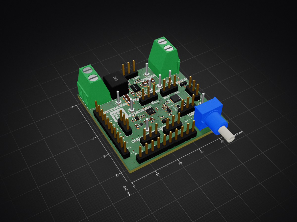
This repository contains design files for the development board for a flashlight boost driver. The test firmware can be found in the firmware repository.
Flashlight is an open-source printed circuit board by engineerbo, from the engineerbo/flashlight-dev-hw repository on GitHub, published under the MIT licence. It is a 4-layer board of 44.5 × 44.5 mm with 73 parts on 51 nets, routed with 367 tracks and 131 vias.
It is built around the ATTINY1616-MN, MP3432GL-Z and 2N7002K, with the 3310C-001-104L, DMC2400UV and ISZ065N03L5SATMA1 among its other parts. Its parts include 24 resistors, 18 capacitors, 5 connectors, 4 ICs and 4 transistors. It belongs with the AVR (ATmega, ATtiny) boards of this library.


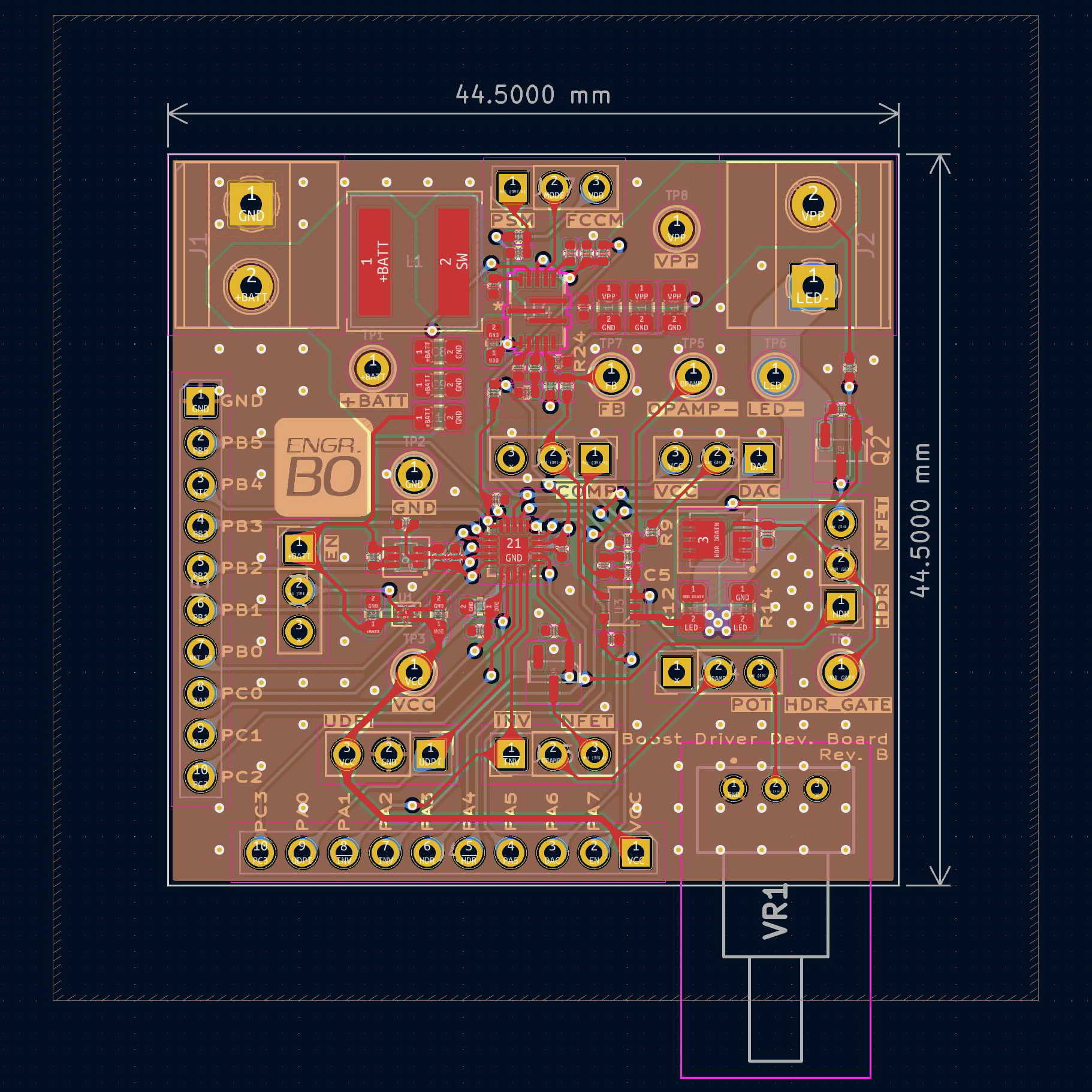
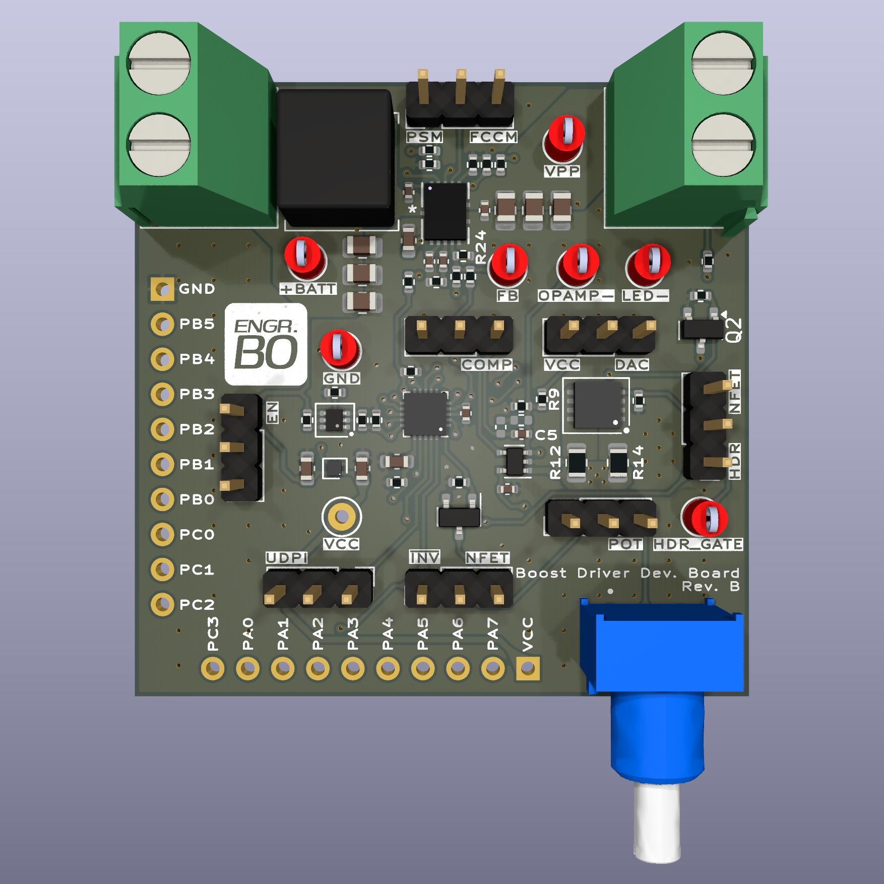
This repository contains design files for the development board for a flashlight boost driver. The test firmware can be found in the firmware repository.
Also included in the scripts subdirectory are Python scripts used to calculate component values during the design process, as well as generate the look-up table for brightness settings.
For a detailed explanation of this project, check out the video series on the Engineer Bo YouTube channel.
The development board is designed in KiCad, and features the following:
This development board is meant to serve as a reference for anybody interested in learning about flashlight boost drivers. It's possible to build these boards, but assembly requires reasonable skill and involves less-than-friendly components e.g. DFN, QFN and many 0402 passives.
Instead, I recommend having a look at the schematics, and leave me a comment on YouTube if you have any questions.
This is the original design built for testing, and includes a couple of issues:
These issues and their fixes are explained in detail in the video series.
Revision B fixes the issues in Revision A:
| Qty | Value | Footprint | References |
|---|---|---|---|
| 8 | 10k | Resistor_SMD:R_0402_1005Metric | R1, R3, R4, R5, R7, R8, R13, TH1 |
| 8 | TestPoint_Probe | TestPoint:TestPoint_Keystone_5000-5004_Miniature | TP1, TP2, TP3, TP4, TP5, TP6, TP7, TP8 |
| 7 | Jumper_3_Bridged12 | Connector_PinHeader_2.54mm:PinHeader_1x03_P2.54mm_Vertical | JP1, JP2, JP3, JP4, JP5, JP6, JP7 |
| 6 | 22uF | Capacitor_SMD:C_0805_2012Metric | C8, C9, C10, C16, C17, C18 |
| 4 | 100nF | Capacitor_SMD:C_0402_1005Metric | C4, C6, C13, C15 |
| 4 | 4.7uF | Capacitor_SMD:C_0603_1608Metric | C1, C2, C3, C11 |
| 2 | 130k | Resistor_SMD:R_0402_1005Metric | R19, R24 |
| 2 | 20k | Resistor_SMD:R_0402_1005Metric | R2, R17 |
| 2 | 2N7002K | Package_TO_SOT_SMD:SOT-23 | Q2, Q4 |
| 2 | 750k | Resistor_SMD:R_0402_1005Metric | R6, R23 |
| 2 | Conn_01x10_Pin | Connector_PinHeader_2.54mm:PinHeader_1x10_P2.54mm_Vertical | J4, J5 |
| 2 | Screw_Terminal_01x02 | TerminalBlock_Phoenix:TerminalBlock_Phoenix_MKDS-1,5-2_1x02_P5.00mm_Horizontal | J1, J2 |
| 1 | 150k | Resistor_SMD:R_0402_1005Metric | R9 |
| 1 | 1R | Resistor_SMD:R_0805_2012Metric | R14 |
| 1 | 2.2uH | Inductor_SMD:L_Coilcraft_XAL7070-XXX | L1 |
| 1 | 22k | Resistor_SMD:R_0402_1005Metric | R20 |
| 1 | 22nF | Capacitor_SMD:C_0402_1005Metric | C12 |
| 1 | 24k | Resistor_SMD:R_0402_1005Metric | R18 |
| 1 | 27k | Resistor_SMD:R_0402_1005Metric | R21 |
| 1 | 3.3nF | Capacitor_SMD:C_0402_1005Metric | C5 |
| 1 | 3310C-001-104L | footprints:3310C001503L | VR1 |
| 1 | 3k3 | Resistor_SMD:R_0402_1005Metric | R10 |
| 1 | 430k | Resistor_SMD:R_0402_1005Metric | R16 |
| 1 | 5mR | Resistor_SMD:R_0805_2012Metric | R12 |
| 1 | 6.8nF | Capacitor_SMD:C_0402_1005Metric | C14 |
| 1 | 6k8 | Resistor_SMD:R_0402_1005Metric | R22 |
| 1 | ATtiny1616-M | Package_DFN_QFN:VQFN-20-1EP_3x3mm_P0.4mm_EP1.7x1.7mm | U2 |
| 1 | Conn_01x03_Pin | Connector_PinHeader_2.54mm:PinHeader_1x03_P2.54mm_Vertical | J3 |
| 1 | DMC2400UV | Package_TO_SOT_SMD_AKL:SOT-563 | Q1 |
| 1 | DNP | Resistor_SMD:R_0402_1005Metric | R15 |
| 1 | DNP | Capacitor_SMD:C_0402_1005Metric | C7 |
| 1 | ISZ065N03L5SATMA1 | Package_SON_AKL:Infineon_PG_TSDSON-8_FL | Q3 |
| 1 | LOGO | Engineer_Bo_Logo:logo_6mm | LOGO1 |
| 1 | MP3432GL-Z | footprints:QFN-13_MP3431_MNP | U4 |
| 1 | NCP114AMX250TCG | Package_DFN_QFN:OnSemi_XDFN4-1EP_1.0x1.0mm_EP0.52x0.52mm | U1 |
| 1 | TLV333/OPA333 | Package_TO_SOT_SMD:SOT-353_SC-70-5 | U3 |
It measures 44.5 × 44.5 mm and has 4 copper layers, 1.6 mm thick.
73 parts, built around the ATTINY1616-MN, MP3432GL-Z, 2N7002K and 3310C-001-104L. The full list of its parts is on this page, with links to each part's symbol and footprint where PCBKit's library has them.
From the engineerbo/flashlight-dev-hw repository on GitHub, at the commit this page was made from: the board is rev_b/flashlight.kicad_pcb and its schematic rev_a/attiny1616.kicad_sch. PCBKit opens the board in the browser, with nothing to install.
Its repository publishes it under the MIT licence: you may reuse it on that licence's terms (keep the author's notice, and for a copyleft licence share your changes alike).


EmielV2002/nRF_dev_board
A dev board utilizing the nRF53 and nPM1100 chip.


loopj/short-stack
World's Smallest Nintendo Wii, using a trimmed motherboard and custom stacked PCBs


kieraneglin/hexagon-art
A passive breakout board: two lever-terminal inputs, three JST XH outputs, all six conductors (RX bus, two spares, +12V, GND, +5V) paralleled straight across. No active components, no regulation, nothing to configure.