4 layers50 × 50 mm
FlightController Drone
damnitzhemanth-oss/Flight_Controller
Custom STM based flightcontroller designed from scratch.
157 parts

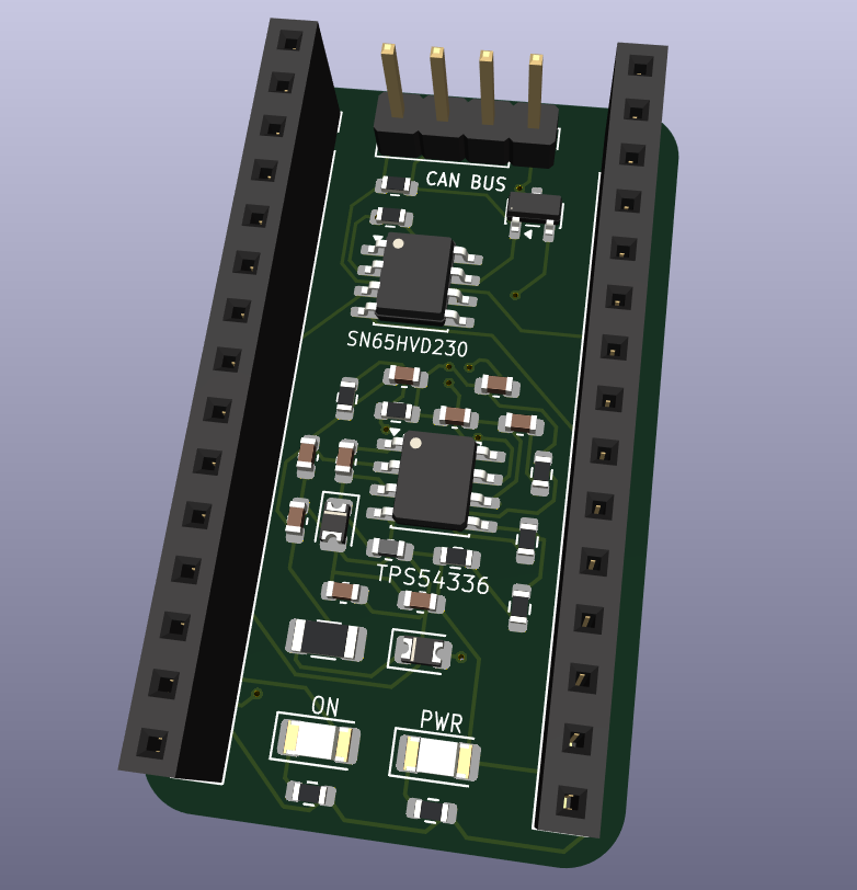
 subbumani12/ESP32_CAN_Shield
A compact ESP32 CAN Shield featuring an SN65HVD230 transceiver, automotive-grade input protection, and an onboard TPS5435A buck converter for reliable CAN bus interfacing.
EspCANshield is an open-source printed circuit board by subbumani12, from the subbumani12/ESP32_CAN_Shield repository on GitHub. It is a 2-layer board of 24 × 41.5 mm with 31 parts on 46 nets, routed with 209 tracks and 13 vias.
It is built around the SN65HVD230D, TPS54336ADDA and NUP2105L. Its parts include 10 resistors, 9 capacitors, 5 diodes, 3 connectors and 2 ICs. It belongs with the power and radio and wireless boards of this library.


A compact ESP32 expansion shield designed to provide reliable and protected CAN bus communication for automotive and industrial applications. The shield integrates a high-speed CAN transceiver, automotive input protection, onboard buck converter, status LEDs, and an ESP32-compatible header for seamless CAN interfacing using the ESP32's built-in TWAI (CAN) controller.
This project implements a custom ESP32 CAN Shield intended for applications requiring robust communication over Controller Area Network (CAN). The board accepts an automotive battery input, converts it to a regulated 3.3 V supply, interfaces directly with an ESP32 development board, and provides protection against common automotive electrical transients.
The hardware has been designed in KiCad with emphasis on simplicity, reliability, and ease of integration with ESP32-based embedded systems.
Vehicle Battery (12–24 V)
          │
          ▼
 Input Protection
 (Fuse + Zener)
          │
          ▼
 TPS5435A Buck Converter
        3.3 V
          │
          ├──────────────► ESP32 Header
          │
          ▼
 SN65HVD230 CAN Transceiver
          │
   CANH / CANL
          │
Vehicle CAN BusThe shield accepts an external automotive battery input through the CAN connector.
Protection circuitry includes:
These components protect the downstream electronics from accidental over-voltage conditions and transient disturbances commonly present in automotive environments.
The board uses the TPS5435ADDAR switching regulator to generate a regulated 3.3 V rail from the vehicle supply.
Main components include:
Advantages of using a switching regulator:
The communication interface is built around the SN65HVD230, a 3.3 V high-speed CAN transceiver.
Features:
The ESP32 handles all CAN protocol processing internally while the transceiver performs physical layer conversion.
The CAN interface includes:
These components improve robustness against electrical transients and provide proper CAN bus termination when required.
A dual-row connector exposes the required GPIOs for an ESP32 development board.
The interface provides:
The shield is intended to work directly with the ESP32's built-in TWAI peripheral without requiring an external CAN controller.
Two onboard LEDs are provided for visual indication.
Possible uses include:
LED functionality can be configured in software.
The hardware consists of five major blocks:
Designed in KiCad
Design considerations:
This project is open-source and intended for educational and research purposes.
| Qty | Value | Footprint | References |
|---|---|---|---|
| 2 | 10n | Capacitor_SMD:C_0603_1608Metric | C3, C6 |
| 2 | 330 | Resistor_SMD:R_0603_1608Metric | R9, R10 |
| 2 | 4.7u | Capacitor_SMD:C_0603_1608Metric | C4, C5 |
| 2 | 47u | Capacitor_SMD:C_0603_1608Metric | C8, C9 |
| 2 | Conn_01x15 | Connector_PinSocket_2.54mm:PinSocket_1x15_P2.54mm_Vertical | J2, J3 |
| 2 | D_Zener | Diode_SMD:D_0805_2012Metric | D2, D3 |
| 2 | LED | LED_SMD:LED_1206_3216Metric | D4, D5 |
| 1 | 0 | Resistor_SMD:R_0603_1608Metric | R6 |
| 1 | 10.2k | Resistor_SMD:R_0603_1608Metric | R7 |
| 1 | 100n | Capacitor_SMD:C_0603_1608Metric | C7 |
| 1 | 10k | Resistor_SMD:R_0603_1608Metric | R1 |
| 1 | 10p | Capacitor_SMD:C_0603_1608Metric | C2 |
| 1 | 120 | Resistor_SMD:R_0603_1608Metric | R2 |
| 1 | 1n | Capacitor_SMD:C_0603_1608Metric | C1 |
| 1 | 29.4k | Resistor_SMD:R_0603_1608Metric | R3 |
| 1 | 3.4k | Resistor_SMD:R_0603_1608Metric | R8 |
| 1 | 332k | Resistor_SMD:R_0603_1608Metric | R4 |
| 1 | 500mA 24V | Fuse:Fuse_1206_3216Metric | F1 |
| 1 | 6.8u | Inductor_SMD:L_0603_1608Metric | L1 |
| 1 | 68.1k | Resistor_SMD:R_0603_1608Metric | R5 |
| 1 | Conn_01x04 | Connector_PinHeader_2.54mm:PinHeader_1x04_P2.54mm_Vertical | J1 |
| 1 | NUP2105L | Package_TO_SOT_SMD:SOT-23 | D1 |
| 1 | SN65HVD230 | Package_SO:SOIC-8_3.9x4.9mm_P1.27mm | U1 |
| 1 | TPS54336ADDA | Package_SO:SOIC-8-1EP_3.9x4.9mm_P1.27mm_EP2.29x3mm | U2 |
damnitzhemanth-oss/Flight_Controller
Custom STM based flightcontroller designed from scratch.

dougsthenri/spindle_driver_v1
PCB project for a BLDC motor driver tailored for CNC spindle motors


santhazsolt/stm32-based-quadcopter-drone
Custom STM32F411 quadcopter flight controller: KiCad PCB, embedded C, ICM-20948 IMU over SPI, quaternion complementary filter, PID attitude control.

zaidhajji/Custom-Flight-Controller-Design-STM32F407-KiCad
Designed a custom flight controller board from schematic to layout: STM32F407VGTx MCU, MPU6050 IMU, BMP280 barometer, MicroSD logging, 6 servo/ESC outputs, and dual-stage power regulation.


GabrielD98/PickUS_and_PlacUS
pick and place de PCB pour projet S4 de robotique

willemcvu/gCAN-gauge
An open-source ESP32-based programmable digital gauge targeted at EV conversions
It measures 24 × 41.5 mm and has 2 copper layers, 1.6 mm thick.
31 parts, built around the SN65HVD230D, TPS54336ADDA and NUP2105L. The full list of its parts is on this page, with links to each part's symbol and footprint where PCBKit's library has them.
From the subbumani12/ESP32_CAN_Shield repository on GitHub, at the commit this page was made from: the board is espCANshield.kicad_pcb and its schematic espCANshield.kicad_sch. PCBKit opens the board in the browser, with nothing to install.
Its repository states no licence, so its author keeps all rights: ask subbumani12 before reusing the design.