
2 layers65 × 56 mm
Toy Ikea MicrowaveController
SkullKill/Toy-Ikea-MicrowaveController-PCB
PCB for Microwave Controller for Ikea Kitchen DUKTIG
73 parts1GPL-3.0

Rpi Dead Man Alarm - PCB and 3D case - Occupancy Monitoring - Raspberry Pi hat
RDMA is an open-source printed circuit board by SkullKill, from the SkullKill/RDMA-PCB repository on GitHub, published under the GPL-3.0 licence. It is a 2-layer board of 65 × 56 mm with 92 parts on 91 nets, routed with 847 tracks and 82 vias.
It is built around the CAT24C32LI-, CC56-12EWA and DS3231MZ/V+, with the HT16K33-28SOP, BSS138 and DMN2056U among its other parts. Its parts include 34 resistors, 12 capacitors, 9 transistors, 8 diodes and 6 connectors.


Rpi Dead Man Alarm - PCB and 3D case - Occupancy Monitoring - Raspberry Pi hat
24-RDMA-Case-04.jpg

23-RDMA-Case-03.jpg

07-RDMAweb-02.jpg

Video of it in action
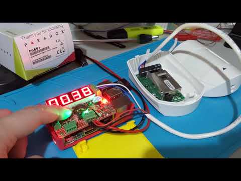
Ready to use PCB Board
https://www.skstore.com.au/electronics/pcb/RDMA
PCB Design Files / gerber files
3D Printed Case design files / STL
https://www.thingiverse.com/thing:4406335
https://www.myminifactory.com/object/3d-print-123446
FYI Gerber files are in the release section
https://github.com/SkullKill/RDMA-PCB/releases
more pictures in the wiki
https://github.com/SkullKill/RDMA-PCB/wiki
18-RDMA-Wiring-01.jpg

10-RDMA-FrontR-V1.0.jpg

15-RDMA-Back-BoardOnly-V1.0.jpg

09-RDMA-schematics-v1.0.jpg

1 to 1 scale
https://github.com/SkullKill/RDMA-PCB/blob/master/Case/RDMAcase-MecanicalDrawing-V1.0.pdf
please use PDF version, and print to scale

PCB features
A 12V , 1A PSU should work, however, to be on the safe side, use a 12V, 2A PSU
Standard wall mount sensor DG65 https://www.paradox.com/Products/default.asp?CATID=8&SUBCATID=79&PRD=1389
swivel mount for DG65 https://www.paradox.com/Products/default.asp?CATID=8&SUBCATID=81&PRD=456
if the service is not running after restarting, GPIO 8 would be on, which would make the buzzer turn on. to turn it off, use the following.
gpio readall
gpio -g mode 8 output
gpio -g write 8 0| Qty | Value | Footprint | References |
|---|---|---|---|
| 13 | 10KΩ | Resistor_SMD:R_0603_1608Metric | R2, R4, R8, R11, R12, R16, R18, R20, R25, R29, R30, R31, R33 |
| 9 | 100nF-50V | Capacitor_SMD:C_0603_1608Metric | C2, C3, C5, C6, C8, C9, C10, C11, C12 |
| 5 | MountingHole | pi-template:MountingHole_2.75mm_M2.5_NoPad | H1, H2, H4, H5, H6 |
| 4 | 100Ω | Resistor_SMD:R_0603_1608Metric | R3, R5, R10, R14 |
| 3 | 1.2KΩ | Resistor_SMD:R_0603_1608Metric | R7, R32, R34 |
| 3 | 2.2KΩ | Resistor_SMD:R_0603_1608Metric | R1, R13, R17 |
| 3 | 22UF-25V | Capacitor_SMD:C_0805_2012Metric | C1, C4, C7 |
| 3 | 330Ω | Resistor_SMD:R_0603_1608Metric | R6, R27, R35 |
| 3 | 4.7KΩ | Resistor_SMD:R_0603_1608Metric | R21, R23, R24 |
| 3 | BSS138 | Package_TO_SOT_SMD:SOT-23 | Q2, Q6, Q7 |
| 3 | DMN2056U | Package_TO_SOT_SMD:SOT-23 | Q3, Q4, Q5 |
| 3 | LED-Yellow | LED_SMD:LED_0603_1608Metric | D3, D6, D11 |
| 3 | SOD1F7 | Diode_SMD:D_SOD-123 | D1, D5, D7 |
| 2 | 3.9KΩ | Resistor_SMD:R_0603_1608Metric | R22, R28 |
| 2 | DMG2305UX | Package_TO_SOT_SMD:SOT-23 | Q1, Q12 |
| 2 | Jumper_3_Bridged12 | Connector_PinHeader_2.54mm:PinHeader_1x03_P2.54mm_Vertical | JP3, JP7 |
| 2 | LED-Green | LED_SMD:LED_0603_1608Metric | D2, D4 |
| 2 | SW_Push | RDMA:SW_SPST_TL3305A | SW2, SW3 |
| 2 | SolderJumper_2_Open | Resistor_SMD:R_0805_2012Metric | JP1, JP2 |
| 1 | 12Vpsu | pi-template:TerminalBlock_bornier-2_P5.08mm | J16 |
| 1 | 1KΩ | Resistor_SMD:R_0603_1608Metric | R19 |
| 1 | 3.3UH-8.5A | pi-template:L_6.3x6.3_H3_HandSolder | L1 |
| 1 | 47KΩ | Resistor_SMD:R_0603_1608Metric | R15 |
| 1 | 57.6KΩ | Resistor_SMD:R_0603_1608Metric | R26 |
| 1 | 5V Reg Sw on-off | Button_Switch_SMD:SW_SPDT_PCM12 | SW1 |
| 1 | Buzzer_Active | RDMA:Buzzer_9x5.5RM5.0 | BZ1 |
| 1 | CAT24C32 | Package_SO:SOIC-8_3.9x4.9mm_P1.27mm | U2 |
| 1 | CC56-12EWA | Display_7Segment:CA56-12EWA | U4 |
| 1 | Coin_1220 | RDMA:BatteryHolder_Keystone_1056_1x1220 | BT1 |
| 1 | DMMT5401 | Package_TO_SOT_SMD:SOT-23-6 | Q11 |
| 1 | DS3231MZ | Package_SO:SOIC-8_3.9x4.9mm_P1.27mm | U5 |
| 1 | HT16K33-28 | Package_SO:SOIC-28W_7.5x17.9mm_P1.27mm | U3 |
| 1 | LOGO | pi-template:skaccessLogo3000 | G*** |
| 1 | LOGO | AAAA-footprint-temp:skaccessLogo2000 | G*** |
| 1 | PTC-2A-16V | Fuse:Fuse_1812_4532Metric_Pad1.30x3.40mm_HandSolder | F1 |
| 1 | ProgrammingJumper | Connector_PinHeader_2.54mm:PinHeader_1x02_P2.54mm_Vertical | J22 |
| 1 | Raspberry_Pi_2_3 | Connector_PinSocket_2.54mm:PinSocket_2x20_P2.54mm_Vertical | J1 |
| 1 | Screw_Terminal_01x04_Left_Bottom | pi-template:TerminalBlock_TE_282834-4_1x04_P2.54mm_Horizontal | J3 |
| 1 | Screw_Terminal_01x06_Top_Right | pi-template:TerminalBlock_TE_282834-6_1x06_P2.54mm_Horizontal | J5 |
| 1 | Screw_Terminal_01x08_Bottom_Left | pi-template:TerminalBlock_TE_282834-8_1x08_P2.54mm_Horizontal | J4 |
| 1 | TPS563200 | Package_TO_SOT_SMD:SOT-23-6_Handsoldering | U1 |
It measures 65 × 56 mm and has 2 copper layers, 1.6 mm thick.
92 parts, built around the CAT24C32LI-, CC56-12EWA, DS3231MZ/V+ and HT16K33-28SOP. The full list of its parts is on this page, with links to each part's symbol and footprint where PCBKit's library has them.
From the SkullKill/RDMA-PCB repository on GitHub, at the commit this page was made from: the board is RDMA/RDMA.kicad_pcb. PCBKit opens the board in the browser, with nothing to install.
Its repository publishes it under the GPL-3.0 licence: you may reuse it on that licence's terms (keep the author's notice, and for a copyleft licence share your changes alike).
SkullKill/Toy-Ikea-MicrowaveController-PCB
PCB for Microwave Controller for Ikea Kitchen DUKTIG

SkullKill/ACYONP-PCB
PCB for Access Control Yubikey OTP NFC Pi (ACYONP). For Raspberry Pi. This is a Door Access Control using Electronic Door Strike, with Yubikey OTP via NFC / KeyPad / WebInterface for Authentication.

hasenbanck/heteromycin
A 3D printer board using a powerfull STM32 MCU, TMC5160/TMC2160 driver and a Raspberry Pi or compatible SBC


pilotniq/MJoulnir
Hardware and software for the control system of a full size electric boat.
