
2 layers98.9 × 78 mm
Siot gateway particle io
simpleiot/hardware
Hardware designs for IoT devices and sensor nodes.
28 parts9Apache-2.0
 simpleiot/hardware9
Hardware designs for IoT devices and sensor nodes.
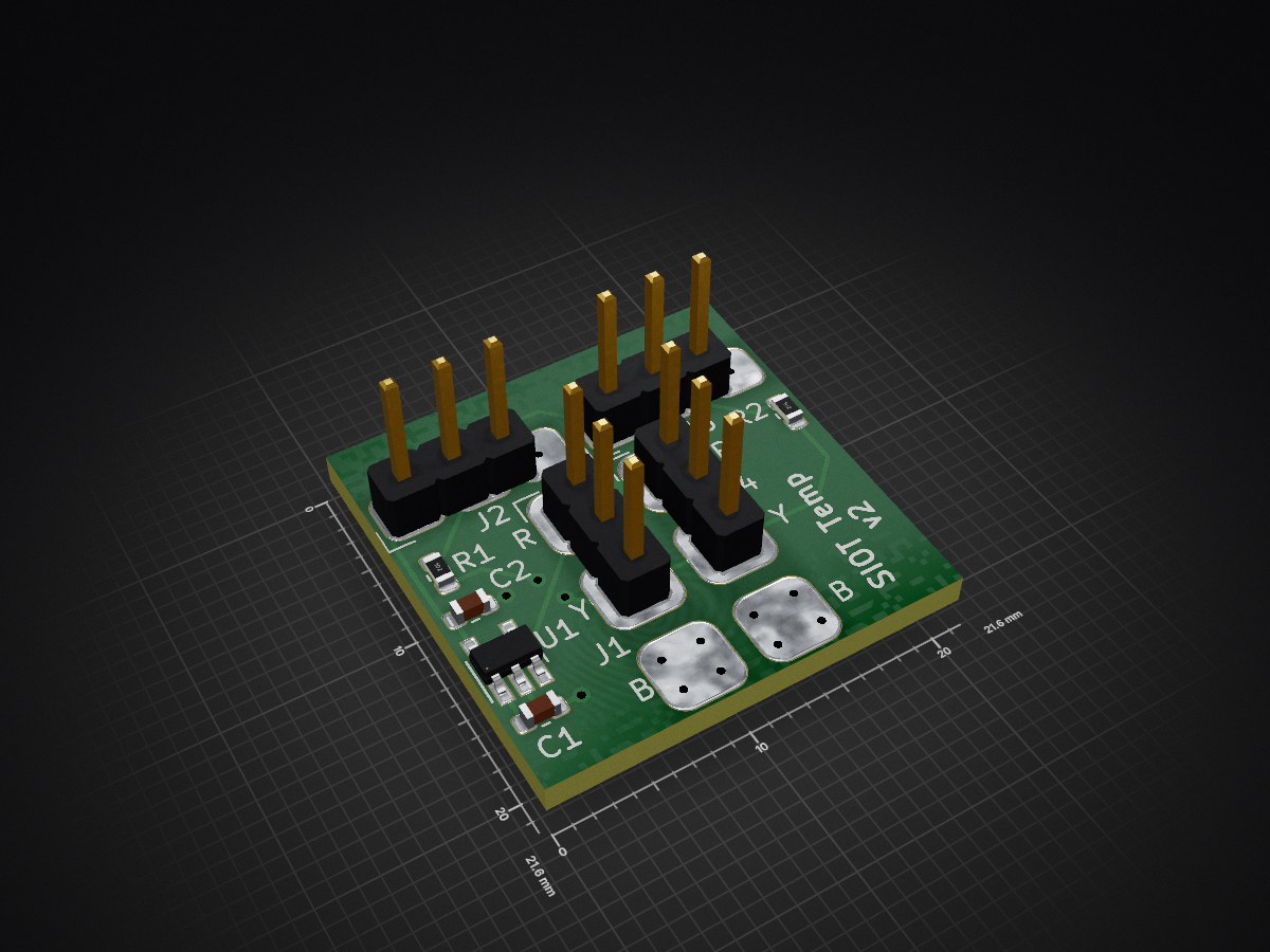
Siot node temp is an open-source printed circuit board by simpleiot, from the simpleiot/hardware repository on GitHub, published under the Apache-2.0 licence. It is a 2-layer board of 21.6 × 21.6 mm with 9 parts on 6 nets, routed with 44 tracks and 14 vias.
It is built around the ADP7142AUJZ-3.3-R7. Its parts include 4 connectors, 2 capacitors, 2 resistors and 1 IC. It belongs with the home automation and IoT boards of this library.
This board is designed to provide a number of expansion features to Raspberry PI and ODROID-C4 SBCs.
There is a UART and SPI ports (todo) wired between the host MPU and the MCU on the expansion board.
A STM32F042K4Tx MCU is used to implement the following functionality:
Reference
Can is typically implemented using a SPI CAN controller (ex MCP2517), but these devices do not offer any buffering so are a poor choice for non real-time operating systems like Linux. Thus, we've chosen to use a MCU to provide the CAN interface and hopefully leverage firmware from the following projects:
| Qty | Value | Footprint | References |
|---|---|---|---|
| 2 | 1K | Resistor_SMD:R_0603_1608Metric | R1, R2 |
| 2 | 2.2uF_50V | Capacitor_SMD:C_0603_1608Metric | C1, C2 |
| 2 | Conn_01x03 | BEC:1x03_solder-pads | J2, J3 |
| 2 | xConnect_smd | BEC:xConnect_smd | J1, J4 |
| 1 | ADP7142AUJZ-3.3 | Package_TO_SOT_SMD:TSOT-23-5 | U1 |
It measures 21.6 × 21.6 mm and has 2 copper layers, 1.6 mm thick.
9 parts, built around the ADP7142AUJZ-3.3-R7. The full list of its parts is on this page, with links to each part's symbol and footprint where PCBKit's library has them.
From the simpleiot/hardware repository on GitHub, at the commit this page was made from: the board is siot-node-temp/siot-node-temp.kicad_pcb. PCBKit opens the board in the browser, with nothing to install.
Its repository publishes it under the Apache-2.0 licence: you may reuse it on that licence's terms (keep the author's notice, and for a copyleft licence share your changes alike).
simpleiot/hardware
Hardware designs for IoT devices and sensor nodes.

simpleiot/hardware
Hardware designs for IoT devices and sensor nodes.

simpleiot/hardware
Hardware designs for IoT devices and sensor nodes.

simpleiot/hardware
Hardware designs for IoT devices and sensor nodes.

simpleiot/hardware
Hardware designs for IoT devices and sensor nodes.

simpleiot/hardware
Hardware designs for IoT devices and sensor nodes.

simpleiot/hardware
Hardware designs for IoT devices and sensor nodes.


lucblender/MIDI-sync-power-dev-board
The MIDI-sync-power-dev-board is a 4hp eurorack module allowing you to get an isolated 5V, 3.3V from LDO, a sync in from 3.5mm jack and either midi input or midi output.

amonbenson/expad
A four-jack USB MIDI adapter for expression and sustain pedals, built on a Raspberry Pi Pico 2 W. It works out what is plugged into each jack - whichever contact a pedal's wiper is on, and whether it is a potentiometer…


oats-center/iot4ag-lorawan-adc-buffer
ADC buffer for the Dragino LoRaWAN module

Karthikpkarthik/Dood_v1
An offline dog "walkie-talkie" inspired by the Galton whistle. Using a local CNN accelerator for voice recognition, the trainer's node spots commands (like "Sit") and sends a character sequence via Meshtastic LoRa mesh…

zeankundev/boards
A collection and an archive of KiCad projects I made. Contains projects from 2023 - 2024.