
2 layers110 × 110 mm

 Serwindev/micromouse
A detailed view of making a micromouse -- absolutely from scratch and with no hardware experience prior.
Schema is an open-source printed circuit board by Serwindev, from the Serwindev/micromouse repository on GitHub. It is a 2-layer board of 90 × 127.1 mm with 37 parts on 42 nets, routed with 248 tracks and 13 vias.
It is built around the DRV8833PW. Its parts include 10 resistors, 4 diodes, 4 transistors, 3 capacitors and 3 connectors. It belongs with the ESP32 boards of this library.
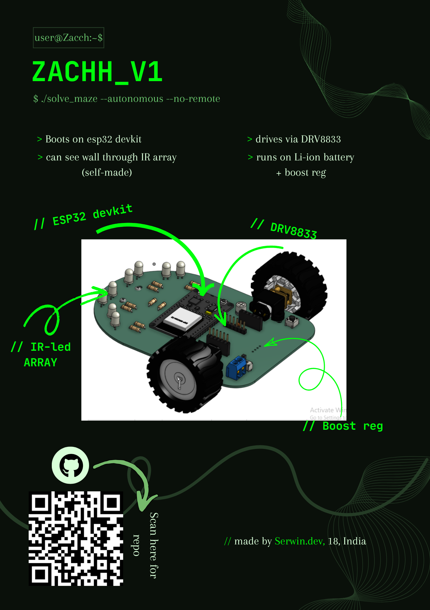
Project Zacch is a full-size micromouse whose aim is to solve the maze autonomously.
The name of the mouse actually comes from Bible (Luke 19:1-10). There was a man called Zacchaeus -- who wanted to see Jesus but because he was short, he couldn't able to see Him. So he climbed a tree to see Jesus.
The dimension of Zacch is 90mm x 127mm (3.54 x 5.00 inches). Compared to other mice out there, it isn't that small. But this is my first-ever hardware project and i needed some more space to work properly.
The Project Zacch v1 is a project made for the event "Fallout" conducted by HackClub.
| sno | product name | description | Quantity | link | unit price | amount | Running total | |
|---|---|---|---|---|---|---|---|---|
| 1 | ESP32 | Brain of the Mouse | 1 | link | 445.00 | 445.00 | 445 | |
| 2 | Motor Driver | Bridge between Brain and motor | 1 | link | 65.00 | 65.00 | 510 | |
| 3 | Motors with encoders | Locomotive device to calculate it's position | 2 | link | 494 | 988 | 1498 | |
| 4 | Infrared Sensors | Eyes to watch out for obstacles | 2 | link | 99.00 | 198 | 1696 | |
| 5 | Battery | To power the mouse | 1 | link | 198 | 198 | 1894 | |
| 6 | MOSFET | To switch on the IR leds | 2 | link | 49.15 | 98.30 | 1992.3 | |
| 7 | Resistors pack | TO limit the current | 1 | link | 199.00 | 199.00 | 2191.3 | |
| 8 | Wheels | Pair of wheels suitable for N20 | 1 | link | 269 | 269 | 2460.3 | |
| 9 | Caster ball | Non-driven wheel to support the mouse | 1 | link | 39 | 39 | 2499.3 | |
| 10 | Boost converter | To convert low voltage into 5v | 1 | link | 87 | 87 | 2586.3 | |
| 11 | Switch | To power ON/OFF | 1 | link | 55 | 55 | 2641.3 | |
| 12 | Screw terminal | To connect battery | 1 | link | 25 | 25 | 2666.3 | |
| 13 | Capacitor 47uF | Caps to store energy | 3 | link | 17.89 | 53.67 | 2719.97 | |
| 14 | Capacitor 0.1uF | Caps | 10 | link | 16.00 | 160 | 2879.97 | |
| 15 | Female headers | To mount componenets | 3 | link | 8.5 | 25.50 | 2905.47 | |
| 16 | Male headers | To mount components | 2 | link | 25 | 50 | 2955.47 | |
| 17 | Tactile switch | To actually make mouse move | 1 | link | 20 | 20 | 2975.47 | |
| 18 | PCB | Acts as a chassis as well as electrical circuit | 1 | wherever you prefer | 3500 | 3500 | 6475.47 | |
| 19 | 3d print | Mounts for motors | 2 | wherever you prefer (use assets/CAD_design/Motot_mount.stp) | 500 | 1000 | 7475.47 |
I have actually journalled everything from Day 1 till the end -- you can find them in the Devlogs folder.
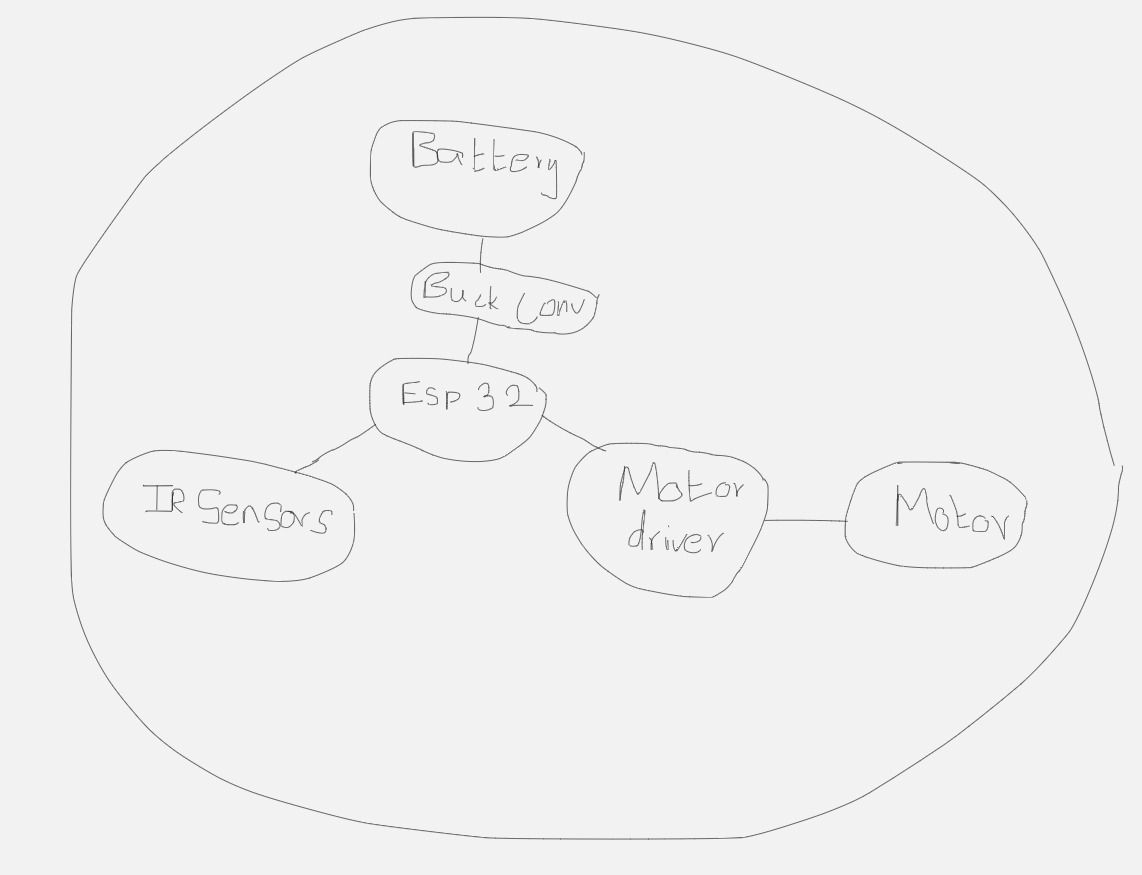
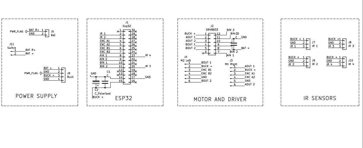
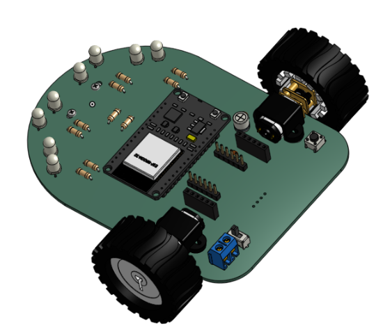
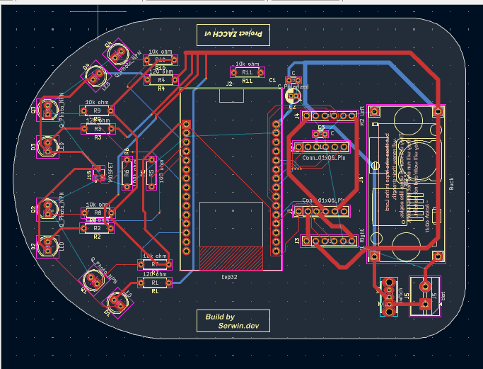
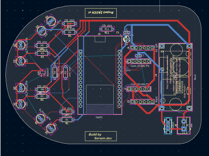
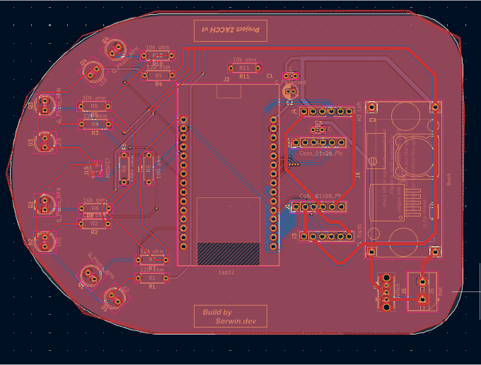
PS: There's an easter egg in the PCB -- if you can find it out and DM me for prizes!! Instagram: @serwin.dev
| Qty | Value | Footprint | References |
|---|---|---|---|
| 4 | 10k ohm | Resistor_THT:R_Axial_DIN0207_L6.3mm_D2.5mm_P7.62mm_Horizontal | R7, R8, R9, R10 |
| 4 | 120 ohm | Resistor_THT:R_Axial_DIN0207_L6.3mm_D2.5mm_P7.62mm_Horizontal | R1, R2, R3, R4 |
| 4 | LED | LED_THT:LED_D5.0mm_Clear | D1, D2, D3, D4 |
| 4 | MountingHole_3.2mm_M3 | MountingHole:MountingHole_3.2mm_M3 | Motor mount, Motor mount, Motor mount, Motor mount |
| 4 | Q_Photo_NPN | LED_THT:LED_D5.0mm_Clear | Q1, Q2, Q3, Q4 |
| 2 | C 0.1 | Capacitor_THT:C_Disc_D3.0mm_W1.6mm_P2.50mm | C1, C3 |
| 2 | MountingHole_2.5mm | MountingHole:MountingHole_2.5mm | Motor mount - ball, Motor mount - ball |
| 1 | 100 ohm | Resistor_THT:R_Axial_DIN0207_L6.3mm_D2.5mm_P7.62mm_Horizontal | R5 |
| 1 | 100k ohm | Resistor_THT:R_Axial_DIN0207_L6.3mm_D2.5mm_P7.62mm_Horizontal | R6 |
| 1 | BOOST | footprints:TPS61023 | Boost conv |
| 1 | Bat | TerminalBlock:TerminalBlock_MaiXu_MX126-5.0-02P_1x02_P5.00mm | Battery |
| 1 | C_Polarized 47 | Capacitor_THT:CP_Radial_D6.3mm_P2.50mm | C2 |
| 1 | DRV8833 | Connector_PinHeader_2.54mm:PinHeader_1x06_P2.54mm_Vertical | J1 |
| 1 | Esp32 | footprints:MODULE_ESP32_DEVKIT_V1 | Esp32 |
| 1 | GND | Connector_PinHeader_2.54mm:PinHeader_1x06_P2.54mm_Vertical | J14 |
| 1 | M1 Right | Connector_PinSocket_2.54mm:PinSocket_1x06_P2.54mm_Vertical | Motor B |
| 1 | M2 Left | Connector_PinSocket_2.54mm:PinSocket_1x06_P2.54mm_Vertical | Motor A |
| 1 | MOSFET | footprints:SOT95P280X125-3N | J15 |
| 1 | Switch | Button_Switch_THT:SW_Slide_SPDT_Straight_CK_OS102011MS2Q | Switch |
| 1 | Tact Switch | Button_Switch_THT:SW_PUSH_6mm_H5mm | Tact Switch |
It measures 90 × 127.1 mm and has 2 copper layers, 1.6 mm thick.
37 parts, built around the DRV8833PW. The full list of its parts is on this page, with links to each part's symbol and footprint where PCBKit's library has them.
From the Serwindev/micromouse repository on GitHub, at the commit this page was made from: the board is kiCad/schema/schema.kicad_pcb and its schematic kiCad/schema/schema.kicad_sch. PCBKit opens the board in the browser, with nothing to install.
Its repository states no licence, so its author keeps all rights: ask Serwindev before reusing the design.

RoboticsBrno/Robutek
Robůtek je robotická platforma založená na čipu ESP32-S3. Je velice rozšitiřelný, ale ze základu umí jezdit, kreslit fixou, jezdit po čáře, pohybovat se bludištěm. Programování je přes Jaculus.


CWRUbotix/Micromouse-2023-24
A fully autonomous maze-solving not-quite-mouse-sized robot.

FIPATECH/CDFR26_PAMI
Open source firmware and PCB for a differential mobile robot (PAMI) based on ESP32-S3 - Coupe de France de Robotique

empriselab/mote
A low cost, high confidence mobile robot optimized for education.

interspecifics/ComunicacionesEspeculativas
Es un proyecto basado en una máquina que es capaz de observar y aprender de microorganismos para crear un score audiovisual a partir de los patrones que encuentre en su comportamiento.

nochkin/esp-line-follower
A simple educational project to build a line following 2WD robot