2 layers97.8 × 43.2 mm
Close door
NadavBenda/close-the-door-analog
A tiny fully-analog, battery-powered behavioral reminder device.
56 parts

 opatiny/micromouse15
Designing a custom micromouse robot.
Ms pcb is an open-source printed circuit board by opatiny, from the opatiny/micromouse repository on GitHub, published under the CERN-OHL-P-2.0 licence. It is a 2-layer board of 110 × 110 mm with 39 parts on 66 nets, routed with 247 tracks and 26 vias.
It is built around the DRV8833PW, PKLCS1212E20A0-R1 and PTS526 SMG15 SMTR2 LFS, with the XT60-M among its other parts. Its parts include 8 resistors, 4 diodes, 3 capacitors, 3 connectors and 2 ICs. It belongs with the robots and motor control boards and the ESP32 boards of this library.


YouTube demo of the project: https://youtu.be/nz4QlaSIkbY
Main repository for my bachelor's thesis project.
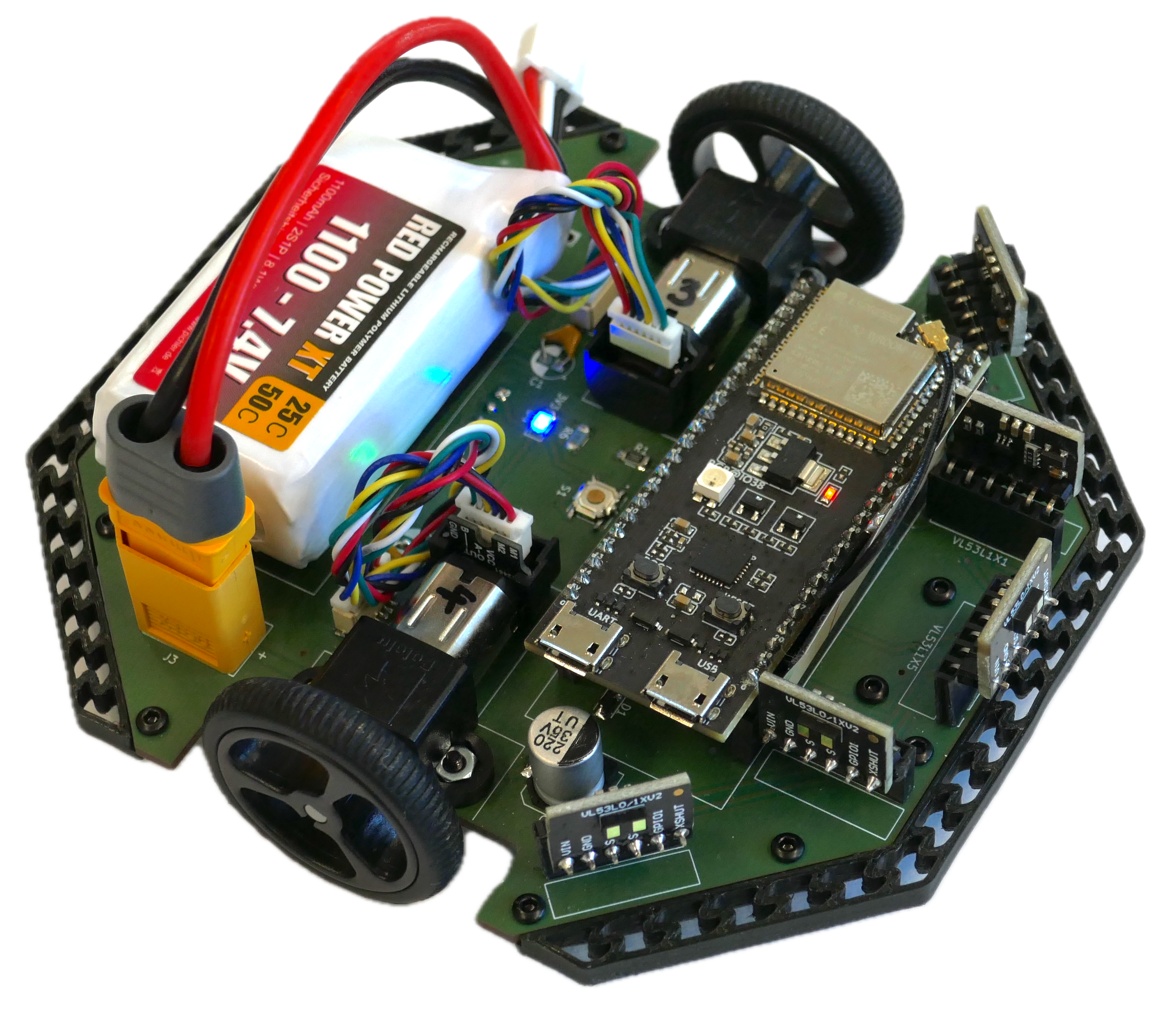
The software fo this robot can be found in the two following repositories:
This project was inspired by the micromouse competitions, in which small autonomous maze-solving robots compete to solve an unknown maze in the shortest possible time. The main focus of the project was to design a micromouse from scratch, which implied electrical and mechanical design, as well as the manufacturing of our own custom PCB. A physical prototype of the robot was fully assembled and tested. The robot implements 5 ToF distance sensors, an accelerometer and two brushed DC motors with encoders. The microcontroller is an ESP32-S3, and a 2P1S LiPo battery is used as a power supply. On the software side, all of the sensors were tested independently and are functional. A basic odometry task was also implemented, which allows to track the robot's position, and speed regulation of the wheels was added. What is more, a remote debug interface using WiFi was programmed in order to visualize the robot's status in real time.
The report of this thesis can be found in the docs folder of this repository: bachelor-thesis-opatiny.pdf
These are the main folders in this repository:
docs: All sorts of documentation about the project, as well as the datasheets and useful images of the components used.electronics: Contains all the KiCad files of the PCB.mechanics: All files related to mechanical design and manufacturing. Also contains all of our custom maze files.matlab: Calculations and plot realized during the project.software: Not the actual micro-controller software. This only contains a few tests done using the Micromouse Simulator tool.All the software of the robot is in its own repository: opatiny/ms-software.
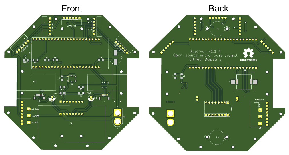
The robot's PCB was fully designed in KiCad. The list of all the components used can be found in docs/electronics/mouseHardware.md.
Render of the final PCB
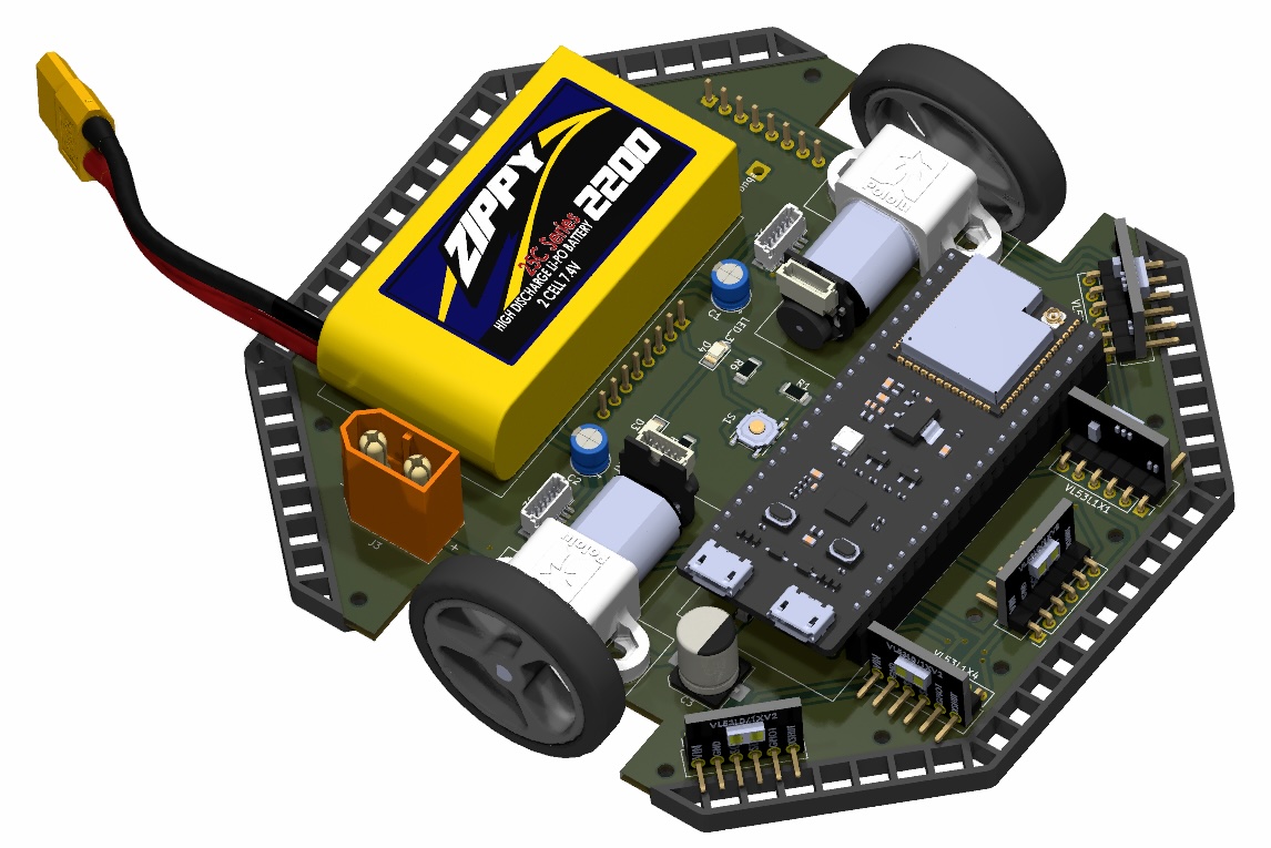
3D view of the completed robot
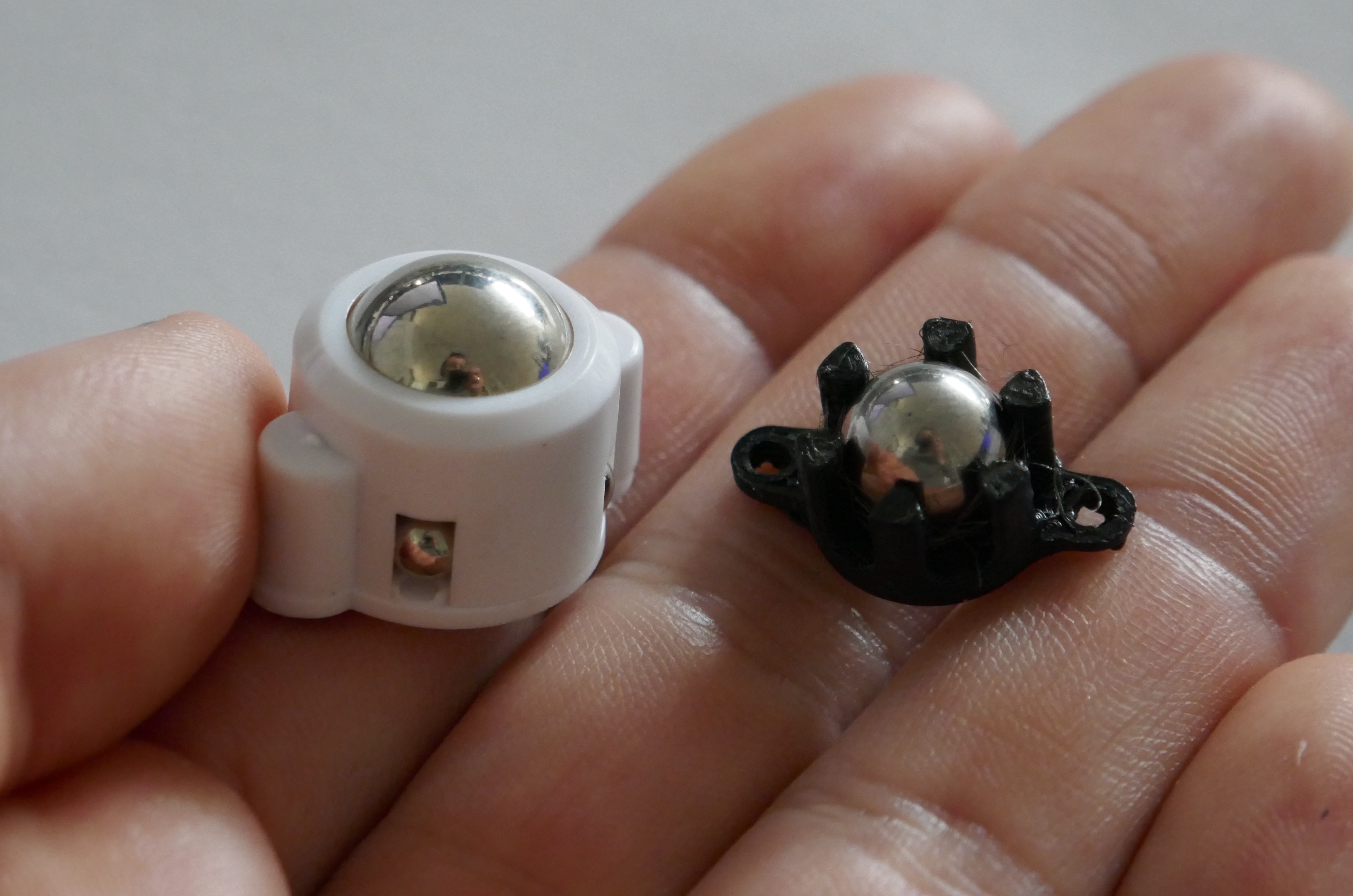
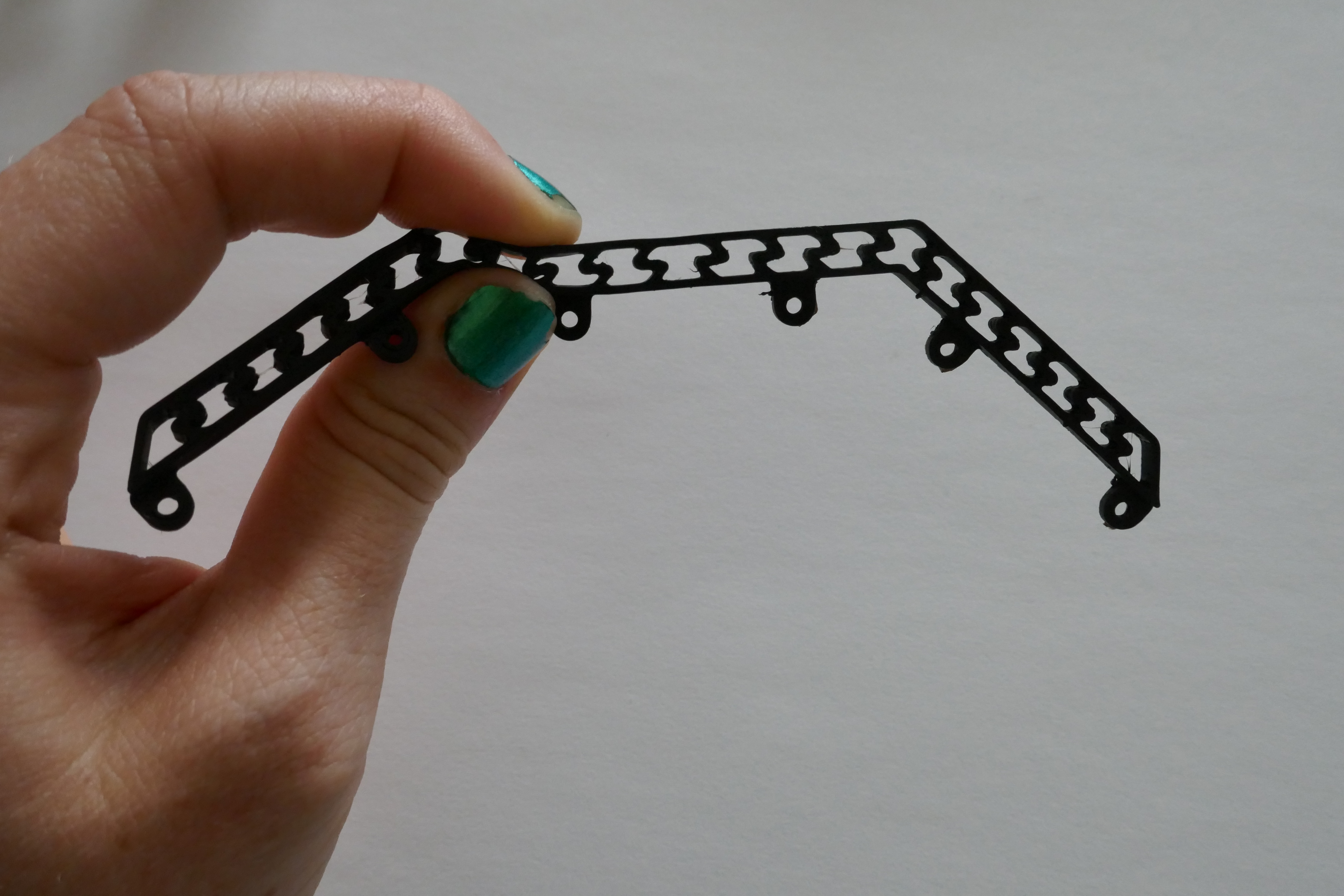
The mechanical design is relatively simple since the PCB is the main structural element. We just had to design our own caster wheel, that are 3D printed out of PETG, and custom bumpers, 3D printed out of flexible filament.
Comparison of commercial and custom caster wheel
Close-up of the bumper
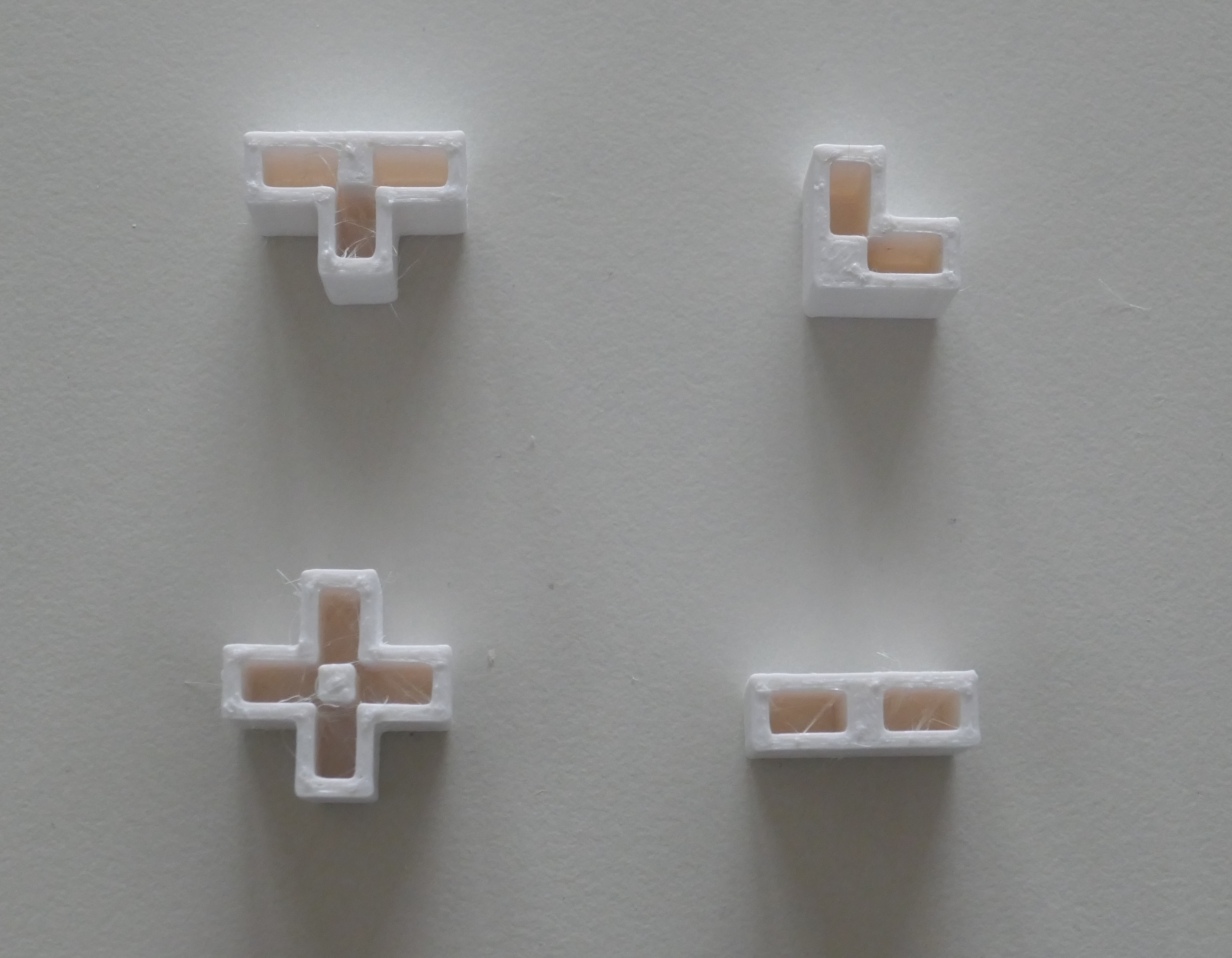
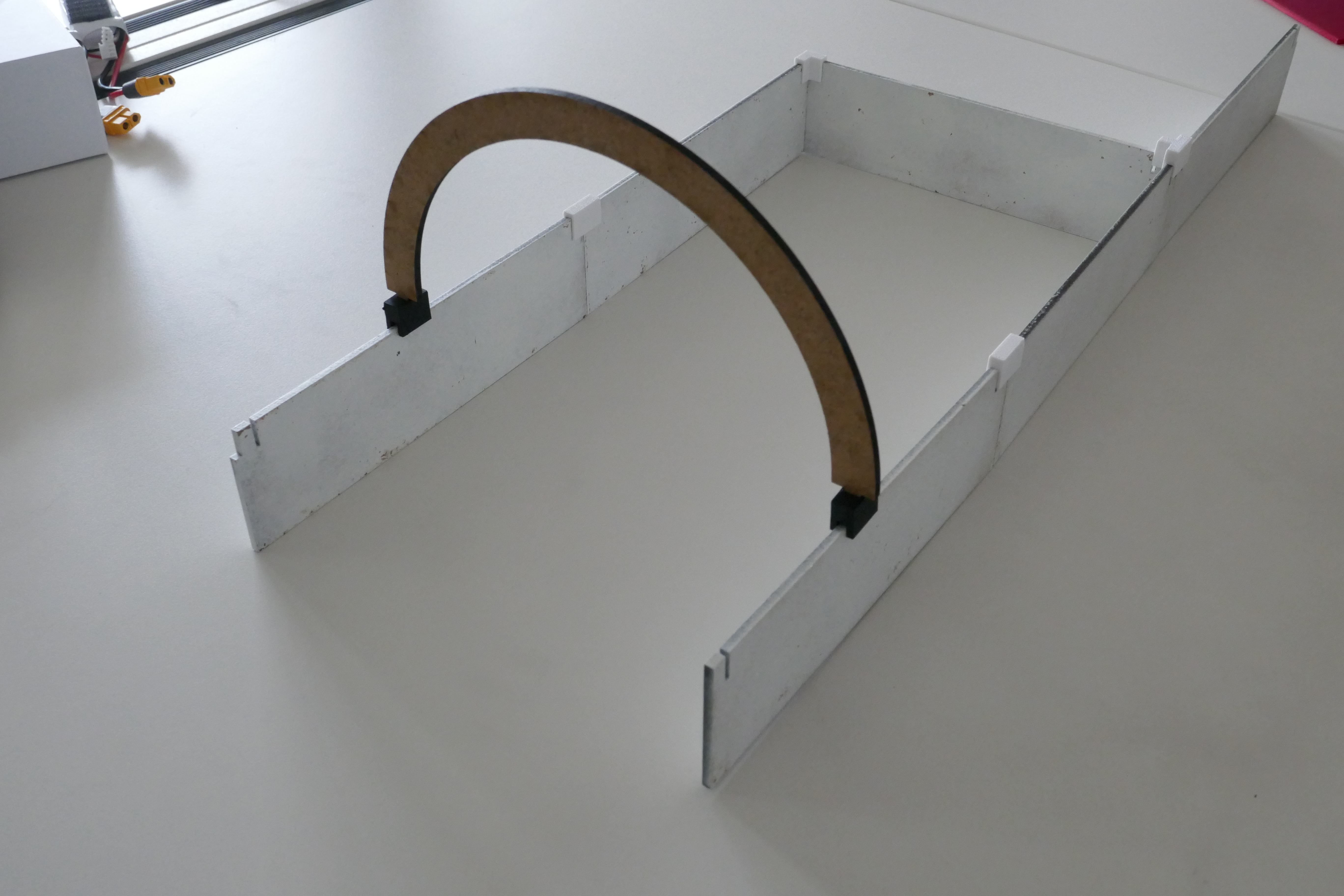
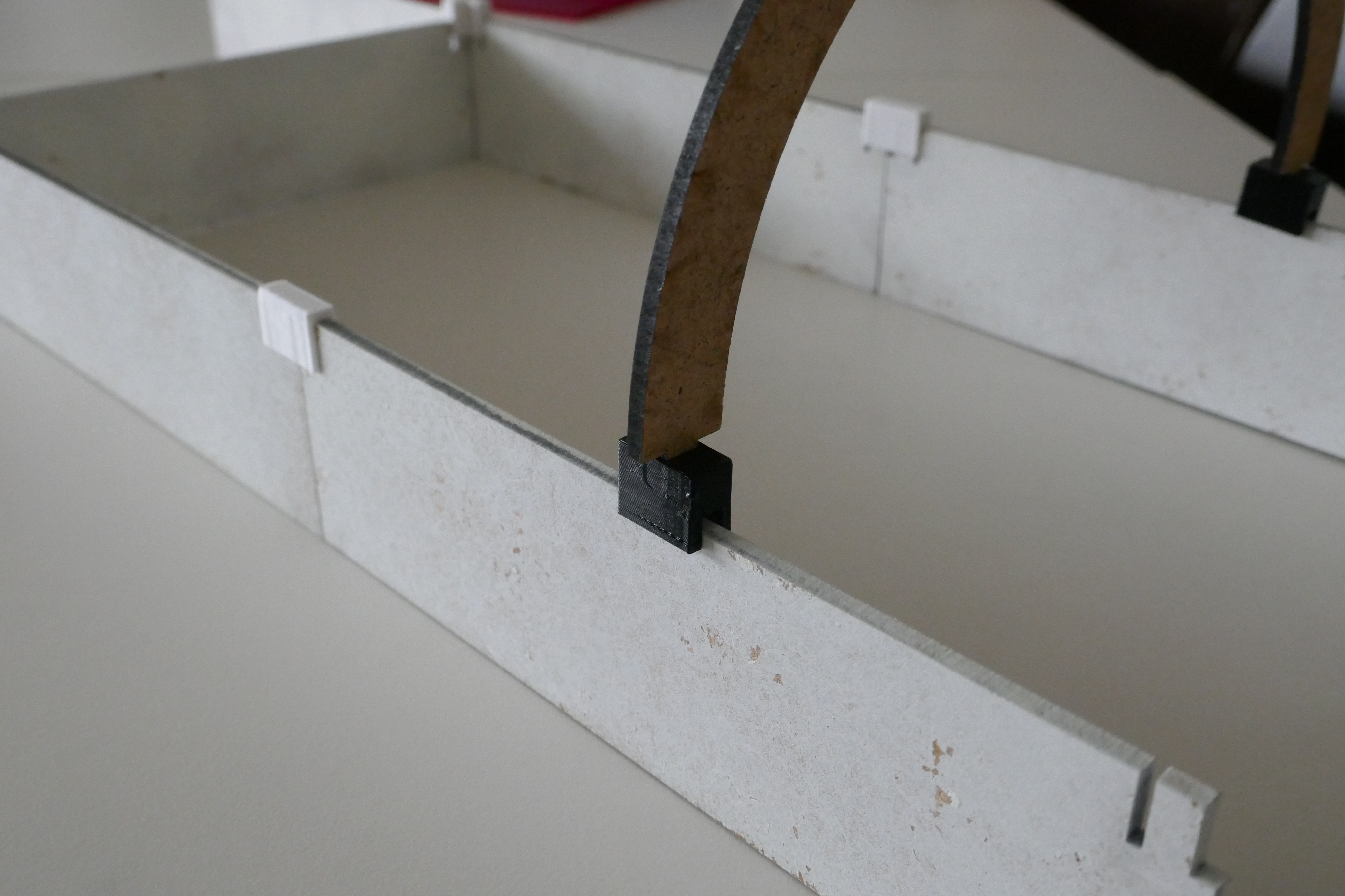
In order to test our robot, we designed our own maze. The walls are 3mm MDF, spray painted white. The connectors are 3D printed out of PETG. Additional "bridge" parts are use to ensure the walls are parallel, and at the right distance from each other. All the parts were designed in solidworks.
The four types of connectors
Example of a small section of maze, integrating one of the "bridge" parts
| Qty | Value | Footprint | References |
|---|---|---|---|
| 3 | 10k | Resistor_SMD:R_1206_3216Metric_Pad1.30x1.75mm_HandSolder | R2, R3, R4 |
| 2 | 0.1uF | Capacitor_THT:CP_Radial_D5.0mm_P2.00mm | C1, C2 |
| 2 | 1k | Resistor_SMD:R_1206_3216Metric_Pad1.30x1.75mm_HandSolder | R7, R8 |
| 2 | Caster_wheel | footprints:caster_wheel_custom | H5, H6 |
| 2 | Motor_holes | footprints:Polulu_Micro_Gearmotor | H3, H4 |
| 1 | 20k | Resistor_SMD:R_1206_3216Metric_Pad1.30x1.75mm_HandSolder | R1 |
| 1 | 220uF | Capacitor_SMD:CP_Elec_8x10.5 | C3 |
| 1 | 40k | Resistor_SMD:R_1206_3216Metric_Pad1.30x1.75mm_HandSolder | R5 |
| 1 | 5k | Resistor_SMD:R_1206_3216Metric_Pad1.30x1.75mm_HandSolder | R6 |
| 1 | Battery | footprints:LiPo_2S1P_Battery | BT1 |
| 1 | Bumper_back | footprints:Micromouse_bumper | H2 |
| 1 | Bumper_front | footprints:Micromouse_bumper | H1 |
| 1 | DEBUG | LED_SMD:LED_1206_3216Metric_Pad1.42x1.75mm_HandSolder | D2 |
| 1 | DRV8833 | footprints:Polulu_DRV8833 | DRV1 |
| 1 | D_Schottky | Diode_SMD:D_1206_3216Metric_Pad1.42x1.75mm_HandSolder | D1 |
| 1 | Debug_3.3V | Connector_Wire:SolderWire-0.75sqmm_1x01_D1.25mm_OD2.3mm | H7 |
| 1 | Debug_GND | Connector_Wire:SolderWire-0.75sqmm_1x01_D1.25mm_OD2.3mm | H9 |
| 1 | Debug_VBAT | Connector_Wire:SolderWire-0.75sqmm_1x01_D1.25mm_OD2.3mm | H8 |
| 1 | ESP32-S3-DEVKITC-1U-N8R2 | footprints:XCVR_ESP32-S3-DEVKITC-1U-N8R2 | U1 |
| 1 | Front | footprints:TinyTronics_VL53L1X_header_front | VL53L1X5 |
| 1 | Front-left | footprints:TinyTronics_VL53L1X | VL53L1X3 |
| 1 | Front-right | footprints:TinyTronics_VL53L1X | VL53L1X2 |
| 1 | GY-521 | footprints:GY-521 | U2 |
| 1 | LED_3V3 | LED_SMD:LED_1206_3216Metric_Pad1.42x1.75mm_HandSolder | D4 |
| 1 | LED_VBAT | LED_SMD:LED_1206_3216Metric_Pad1.42x1.75mm_HandSolder | D3 |
| 1 | Left | footprints:TinyTronics_VL53L1X | VL53L1X1 |
| 1 | Left motor | footprints:JST_SH_6pins | J1 |
| 1 | PKLCS1212E20A0-R1 | footprints:buzzer_double_footprint | LS1 |
| 1 | PTS526_SMG15_SMTR2_LFS | footprints:SW_PTS526_SMG15_SMTR2_LFS | S1 |
| 1 | Right | footprints:TinyTronics_VL53L1X | VL53L1X4 |
| 1 | Right motor | footprints:JST_SH_6pins | J2 |
| 1 | XT60-M | footprints:AMASS_XT60-M | J3 |
The 38 most common of 39 parts.
It measures 110 × 110 mm and has 2 copper layers, 1.6 mm thick.
39 parts, built around the DRV8833PW, PKLCS1212E20A0-R1, PTS526 SMG15 SMTR2 LFS and XT60-M. The full list of its parts is on this page, with links to each part's symbol and footprint where PCBKit's library has them.
From the opatiny/micromouse repository on GitHub, at the commit this page was made from: the board is electronics/ms-pcb.kicad_pcb and its schematic electronics/ms-pcb.kicad_sch. PCBKit opens the board in the browser, with nothing to install.
Its repository publishes it under the CERN-OHL-P-2.0 licence: you may reuse it on that licence's terms (keep the author's notice, and for a copyleft licence share your changes alike).
NadavBenda/close-the-door-analog
A tiny fully-analog, battery-powered behavioral reminder device.

Mig-M27/Avionics-PCBs
Este repositório é usado para gerir as versões dos projetos KiCAD do sistema de Avionics da Porto Space Team. Está dividido em 2 secções: 1.

Adityawadpalliwar/smart-hydration-reminder-PCB
A compact, low-power, wireless-capable PCB designed to live in a water bottle base or sleeve. It detects when you drink using a 6-axis IMU, keeps a running record of intake events, and reminds you with a buzzer when you…

AshiqAshref/Garage-Door-Opener
Universal Garage Door using BLE (Bluetooth Low Power) running on ESP32 with highest security possible.

hoodnoah/woodstove_monitor
An ESP32-based temperature monitor and logger for stack temperature of a woodstove, written in Rust.

RoboticsBrno/Robutek
Robůtek je robotická platforma založená na čipu ESP32-S3. Je velice rozšitiřelný, ale ze základu umí jezdit, kreslit fixou, jezdit po čáře, pohybovat se bludištěm. Programování je přes Jaculus.


CWRUbotix/Micromouse-2023-24
A fully autonomous maze-solving not-quite-mouse-sized robot.