Skip to the content
PCBKitNew board
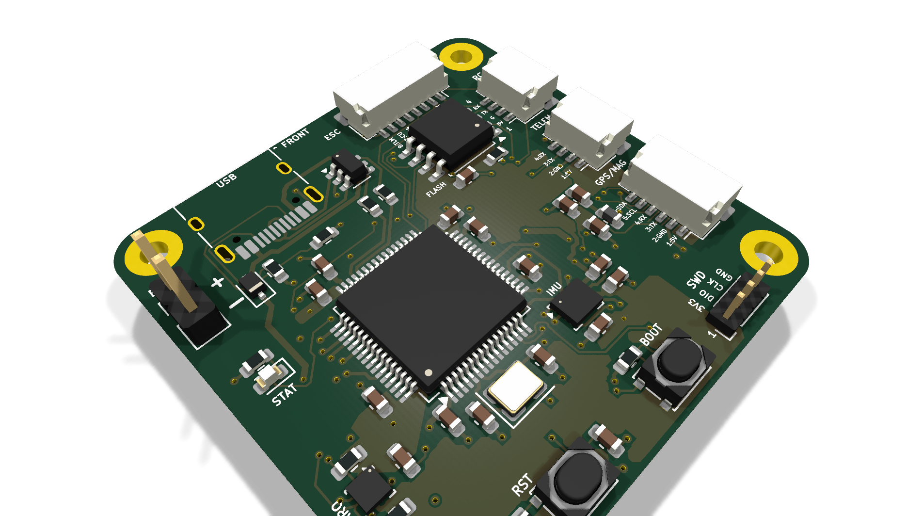
4 layers40 × 40 mmAeroHawk FC, the printed circuit board in 3D

The Eagle: Custom STM32F405 4-Layer Autonomous Avionics Flight Controller PCB

Size
40 × 40 mm
Copper layers
4
Thickness
1.6 mm
Parts
76
Nets
80
Pads
297
Tracks, vias
1,094, 128
Pours
12
Routed
Yes
KiCad
KiCad 10.0 (file 20260206)
Created
6 Oct 2026
Updated
15 Oct 2026

Overview

AeroHawk FC is an open-source printed circuit board by sbbxiii, from the sbbxiii/The-Eagle repository on GitHub, published under the MIT licence. It is a 4-layer board of 40 × 40 mm with 76 parts on 80 nets, routed with 1,094 tracks and 128 vias.

It is built around the STM32F405RGT6, BMP390 and W25Q128JVSIQ, with the ICM-42688-P, TLV75733PDBVR-MS and USBLC6-2SC6 among its other parts. Its parts include 27 capacitors, 18 resistors, 7 ICs, 7 connectors and 6 diodes. It belongs with the robots and motor control boards and the STM32 boards of this library.

Main components

12

README

README.md

The Eagle: Custom STM32F405 Autonomous Flight Controller

KiCad Version Hardware Architecture DRC Status [blocked] Firmware Support [blocked] License

The Eagle is a custom, 4-layer high-reliability avionics flight controller (FC) designed around the STMicroelectronics STM32F405RGT6 microcontroller. Engineered for autonomous Unmanned Aerial Vehicles (UAVs) and high-performance robotics platforms, the board integrates high-bandwidth IMU telemetry, multi-stage power conditioning, blackbox high-rate logging, and deterministic motor signaling into a 40.0 × 40.0 mm board footprint with a 34.0 × 34.0 mm mounting hole pattern.


3D Isometric View

The Eagle Isometric Render


Hardware Gallery & Subsystems

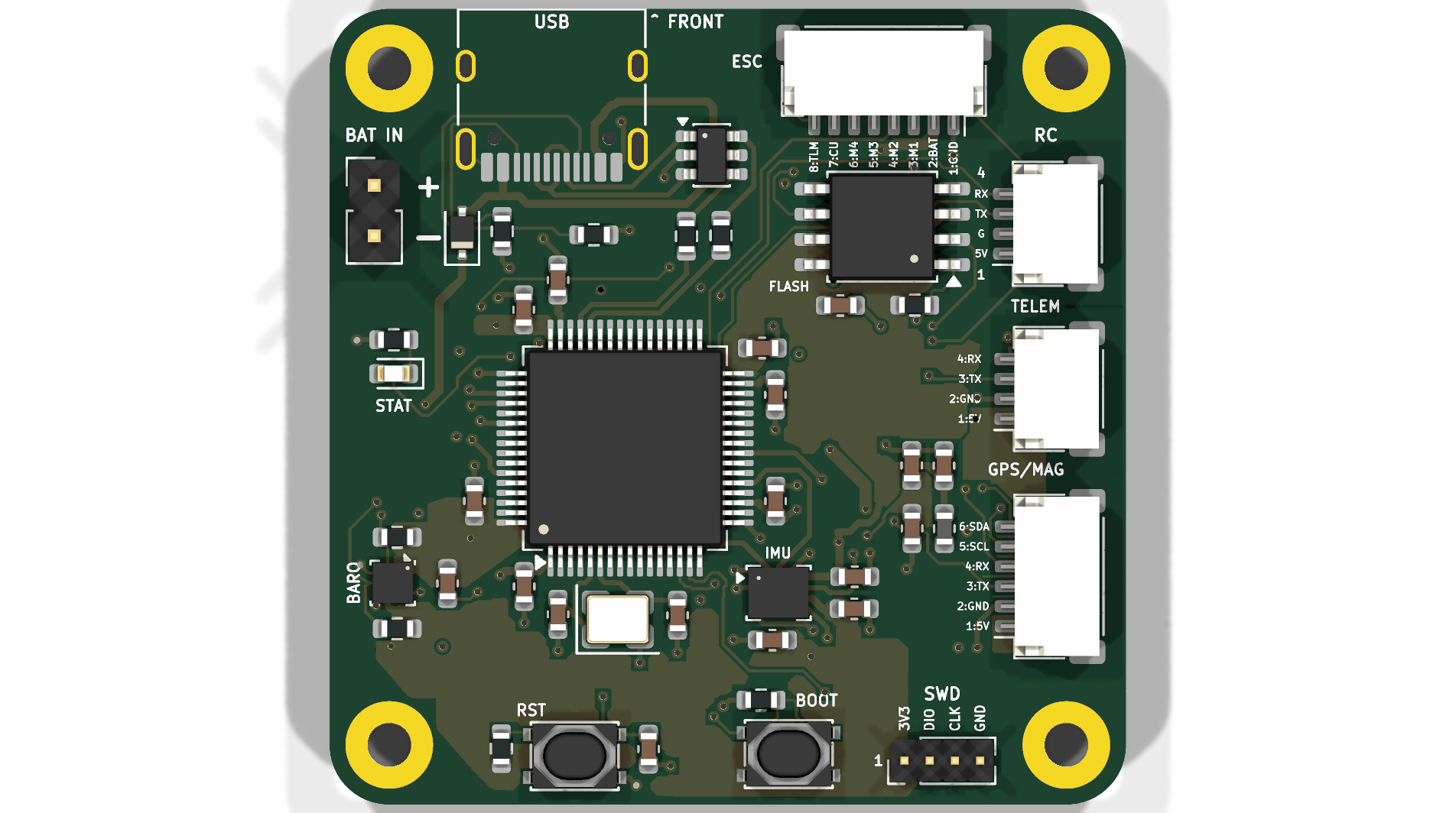
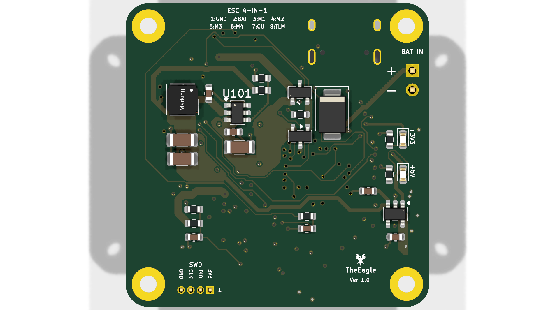
Top View (Components & Silicon)Bottom View (Power Stages & Silkscreen)
Top ViewBottom View
MCU, IMU, Baro, Flash, SWD, and I/O headersBuck Regulator, LDO, TVS Diode, Reverse-Polarity FET, ESC pads

Engineering Highlights & Key Specifications

1. Compute & Core Architecture

  • Primary MCU: STM32F405RGT6 (ARM Cortex-M4 with single-precision FPU, 168 MHz core clock, 1 MB Flash, 192 KB SRAM).
  • Clocking: External 8.000 MHz crystal oscillator feeding the internal PLL for zero-jitter core timing and USB 48 MHz generation.
  • Programming & Debug: Onboard 4-pin SWD header (3V3, SWDIO, SWCLK, GND) for ST-Link / J-Link debugging and automated CI flashing.
  • Boot Management: Hardware BOOT and RST tactile buttons supporting USB DFU system recovery.

2. Sensor Suite & Signal Integrity

  • Primary IMU: TDK InvenSense ICM-42688-P 6-axis MEMS gyroscope/accelerometer on a dedicated high-speed SPI1 bus (up to 20 MHz).
  • Interrupt Routing: Dedicated hardware EXTI Data-Ready (DRDY) interrupt line tied directly to the MCU NVIC for deterministic 8 kHz loop timing.
  • Barometric Altimeter: Bosch Sensortec BMP390 precision pressure sensor on I2C1 for sub-meter altitude hold.
  • Blackbox Storage: Winbond W25Q128JVSSIQ (128 Mbit / 16 MB) SPI NOR Flash on SPI3 for high-rate loop and telemetry logging.
  • Bus Isolation: SPI and I2C signal traces are referenced directly to an unbroken Layer 2 Ground Plane to suppress crosstalk and high-frequency noise.

3. Power Distribution Network (PDN)

  • Battery Input: 3S–6S LiPo input (9.0V to 26.0V nominal; rated up to 36V transient tolerance).
  • Transient Voltage Suppression (TVS): Onboard SMBJ28A high-energy TVS clamp at the main battery junction to suppress motor inductive voltage spikes.
  • Reverse Polarity Protection: P-channel MOSFET gate protection preventing accidental battery reverse-connection damage.
  • Synchronous Buck Converter: Texas Instruments LMR51430 step-down regulator delivering clean 5.0V @ 3.0A for receivers, telemetry, and peripheral rails.
  • Ultra-Low-Noise Sensor LDO: Texas Instruments TLV75733PDBV (3.3V @ 1.0A) high-PSRR linear regulator exclusively isolating the analog sensors and MCU core.
  • Analog Telemetry: Low-pass RC filtered 11:1 voltage divider (VBAT_SENSE) and ESC analog current input (CURR_SENSE).
  • USB Interface: Micro-USB / USB-C pads protected by ST USBLC6-2SC6 ultra-low capacitance bidirectional ESD suppressor.

Silicon Registry & Pin Allocation Matrix

PinFunctionPeripheral BusAlternate FunctionPurpose / Notes
PA0CURR_SENSEADC1ADC1_IN0Analog current sensing from ESC
PA1VBAT_SENSEADC1ADC1_IN111:1 voltage divider battery monitor
PA4IMU_CSGPIOOutputActive-Low SPI Chip Select (ICM-42688-P)
PA5IMU_SCKSPI1SPI1_SCKHigh-speed IMU clock (up to 20 MHz)
PA6IMU_MISOSPI1SPI1_MISOIMU Master In / Slave Out
PA7IMU_MOSISPI1SPI1_MOSIIMU Master Out / Slave In
PB0MOTOR_1TIM3TIM3_CH3Motor 1 output (DShot300/600 / PWM with DMA)
PB1MOTOR_2TIM3TIM3_CH4Motor 2 output (DShot300/600 / PWM with DMA)
PB4MOTOR_3TIM3TIM3_CH1Motor 3 output (DShot300/600 / PWM with DMA)
PB5MOTOR_4TIM3TIM3_CH2Motor 4 output (DShot300/600 / PWM with DMA)
PB6I2C1_SCLI2C1I2C1_SCLBarometer (BMP390) & External Magnetometer
PB7I2C1_SDAI2C1I2C1_SDABarometer (BMP390) & External Magnetometer
PB10UART3_TXUSART3USART3_TXESC Telemetry / Auxiliary Serial
PB11UART3_RXUSART3USART3_RXESC Telemetry / Auxiliary Serial
PA9UART1_TXUSART1USART1_TXHigh-speed Telemetry / Radio Control link
PA10UART1_RXUSART1USART1_RXHigh-speed Telemetry / Radio Control link
PA2UART2_TXUSART2USART2_TXGPS Receiver (UBX / NMEA protocol)
PA3UART2_RXUSART2USART2_RXGPS Receiver (UBX / NMEA protocol)
PC10FLASH_SCKSPI3SPI3_SCKBlackbox Flash Clock
PC11FLASH_MISOSPI3SPI3_MISOBlackbox Flash Data Out
PC12FLASH_MOSISPI3SPI3_MOSIBlackbox Flash Data In
PD2FLASH_CSGPIOOutputBlackbox Flash Chip Select (W25Q128)
PA11USB_DMUSB OTG FSOTG_FS_DMUSB D- with ESD Clamping
PA12USB_DPUSB OTG FSOTG_FS_DPUSB D+ with ESD Clamping
PA13SWDIOSWDSWDIOSerial Wire Debug Data
PA14SWCLKSWDSWCLKSerial Wire Debug Clock

PCB Stackup & Fabrication Rules

  • Dimensions: 40.00 mm × 40.00 mm outer footprint
  • Mounting Pattern: 34.00 mm × 34.00 mm grid (M2 mounting pads)
  • Layer Count: 4 Layers (Standard 1.6 mm FR-4 Stackup):
    • Layer 1 (Top): Component placement & High-Speed Signal routing
    • Layer 2 (Inner 1): Solid Ground Plane (GND) for low return-loop inductance
    • Layer 3 (Inner 2): Power Plane split (5.0V / 3.3V power distribution)
    • Layer 4 (Bottom): Power Switching Stages, ESC pads, and secondary signal traces
  • Minimum Trace / Space: 0.15 mm / 0.15 mm (6 mil / 6 mil)
  • Minimum Drill: 0.3 mm (via size: 0.6 mm outer diameter)
  • Design Rule Check (DRC): 0 Errors, 0 Unconnected Nets

Manufacturing & Project Deliverables

All production assets are pre-generated and included in this repository:


Firmware Compatibility

The hardware layout and pin allocation strictly adhere to the STM32 timer and peripheral mapping required by standard flight controller firmware:

  1. ArduPilot (ChibiOS): Fully compatible via standard ChibiOS hwdef.dat board definition.
  2. Betaflight / INAV: Compatible using STM32F405 target configuration with DShot DMA timer assignment.
  3. Custom Bare-Metal C++ / MATLAB Simulink: Direct code generation via Embedded Coder / HAL drivers using the onboard SWD debug interface.

How to Open in KiCad

  1. Clone this repository:
    bash
    git clone https://github.com/sbbxiii/The-Eagle.git
    cd The-Eagle/hardware
  2. Open AeroHawk_FC.kicad_pro using KiCad 8.0 or newer (tested on KiCad 10.0).
  3. View schematics in Eeschema or board layout in Pcbnew.

Author & License

Designed by Osakwe Nmesoma Chukwukadibia, Bsc Engineering Student University of Debrecen.

Licensed under the MIT License.

Parts

76
QtyValueFootprintReferences
12100nFCapacitor_SMD:C_0603_1608MetricC108, C109, C201, C202, C203, C204, C207, C212, C301, C303, C304, C305
41uF 10VCapacitor_SMD:C_0603_1608MetricC106, C206, C213, C302
4MountingHoleMountingHole:MountingHole_2.2mm_M2_PadH1, H2, H3, H4
310kResistor_SMD:R_0603_1608MetricR202, R203, R303
31kResistor_SMD:R_0603_1608MetricR106, R107, R407
20.1uF 50VCapacitor_SMD:C_0603_1608MetricC102, C103
22.2kResistor_SMD:R_0603_1608MetricR301, R302
22.2uF 16VCapacitor_SMD:C_0603_1608MetricC208, C209
222RResistor_SMD:R_0603_1608MetricR403, R404
222uF 16VCapacitor_SMD:C_1206_3216MetricC104, C105
233pF C0GCapacitor_SMD:C_0603_1608MetricC210, C211
25.1k 1%Resistor_SMD:R_0603_1608MetricR401, R402
1100kResistor_SMD:R_0603_1608MetricR101
1100k 1%Resistor_SMD:R_0603_1608MetricR102
110k 0.1%Resistor_SMD:R_0603_1608MetricR104
110uF 50VCapacitor_SMD:C_1206_3216MetricC101
110uHInductor_SMD_Wurth:L_Wurth_WE-LQSH-4020L101
113.3k 1%Resistor_SMD:R_0603_1608MetricR103
11k 0.1%Resistor_SMD:R_0603_1608MetricR105
12.2uF 10VCapacitor_SMD:C_0603_1608MetricC107
14.7uF 10VCapacitor_SMD:C_0603_1608MetricC205
1470RResistor_SMD:R_0603_1608MetricR108
18.000MHzCrystal:Crystal_SMD_3225-4Pin_3.2x2.5mmY201
1BAT_INConnector_PinHeader_2.54mm:PinHeader_1x02_P2.54mm_VerticalJ101
1BMP390Package_LGA:Bosch_LGA-10_2x2mm_P0.5mmU302
1BZX84C12Package_TO_SOT_SMD:SOT-23D102
1Blue LEDLED_SMD:LED_0603_1608MetricD104
1ESC_4IN1Connector_JST:JST_SH_SM08B-SRSS-TB_1x08-1MP_P1.00mm_HorizontalJ402
1Ferrite Bead (600Ω)Inductor_SMD:L_0603_1608MetricFB201
1GPS_MAGConnector_JST:JST_SH_SM06B-SRSS-TB_1x06-1MP_P1.00mm_HorizontalJ403
1Green LEDLED_SMD:LED_0603_1608MetricD103
1ICM-42688-PPackage_LGA:InvenSense_LGA-14_2.5x3mm_P0.5mmU301
1LMR51430Package_TO_SOT_SMD:SOT-23-6U101
1LOGOLOGOG***
1PMEG3020EJDiode_SMD:D_SOD-323FD401
1Pushbutton (BOOT0)Button_Switch_SMD:SW_Push_SPST_NO_PTS810SW202
1Pushbutton (NRST)Button_Switch_SMD:SW_Push_SPST_NO_PTS810SW201
1RC_RECEIVERConnector_JST:JST_SH_SM04B-SRSS-TB_1x04-1MP_P1.00mm_HorizontalJ405
1Red LEDLED_SMD:LED_0603_1608MetricD403
1SMBJ28CADiode_SMD:D_SMBD101
1STM32F405RGT6Package_QFP:LQFP-64_10x10mm_P0.5mmU201
1SWD_DEBUGConnector_PinHeader_1.27mm:PinHeader_1x04_P1.27mm_VerticalJ201
1Si2319CDSPackage_TO_SOT_SMD:SOT-23Q101
1TELEM_GCSConnector_JST:JST_SH_SM04B-SRSS-TB_1x04-1MP_P1.00mm_HorizontalJ404
1TLV75733PDBVPackage_TO_SOT_SMD:SOT-23-5U102
1USBLC6-2SC6Package_TO_SOT_SMD:SOT-23-6U402
1USB_CConnector_USB:USB_C_Receptacle_HRO_TYPE-C-31-M-12J401
1W25Q128JVSSIQPackage_SO:SOIC-8_5.23x5.23mm_P1.27mmU303

Questions

How big is the AeroHawk FC PCB?

It measures 40 × 40 mm and has 4 copper layers, 1.6 mm thick.

What parts does the AeroHawk FC use?

76 parts, built around the STM32F405RGT6, BMP390, W25Q128JVSIQ and ICM-42688-P. The full list of its parts is on this page, with links to each part's symbol and footprint where PCBKit's library has them.

Where can I download the AeroHawk FC KiCad files?

From the sbbxiii/The-Eagle repository on GitHub, at the commit this page was made from: the board is hardware/AeroHawk_FC.kicad_pcb and its schematic hardware/AeroHawk_FC.kicad_sch. PCBKit opens the board in the browser, with nothing to install.

Can I use the AeroHawk FC design in my own project?

Its repository publishes it under the MIT licence: you may reuse it on that licence's terms (keep the author's notice, and for a copyleft licence share your changes alike).

Similar boards

  • 6 layers29 × 33 mmMINIREX G4, the printed circuit board in 3D

    MINIREX G4

    mathieupommery/MINIREX_G473

    The following table demonstrates the estimated component costs based on Mouser volume pricing. The unit price of each component dynamically adapts to the total quantity required for the entire production batch (1, 100…

    109 parts10
  • 4 layers50.8 × 22.9 mmBench stim wing, the printed circuit board in 3D

    Bench stim wing

    ThatguyCplus/throttleECU

    STM32F411CE Throttle ECU — PID position control with AS5048A encoder, H-bridge motor, safety module

    114 parts1
  • 4 layers175 × 68.5 mmR1000AX, the printed circuit board in 3D

    R1000AX

    pluggee/R1000AX

    Variant A Base Platform Board

    146 parts15GPL-3.0
  • 4 layers165 × 100 mmUsb scoring platform, the printed circuit board in 3D

    Usb scoring platform

    AndrewCraswell/agency

    Native KiCad engineering prototype, separate from the earlier ESP32/tscircuit board. Open usb-scoring-platform.kicadpro in KiCad 10; schematic and PCB are the editable source, with no generator required.

    224 partsMIT
  • 2 layers109 × 126.4 mmRheoBoard v1.05, the printed circuit board in 3D

    RheoBoard v1.05

    The-Hybrid-Atelier/RheoBoard

    RheoBoard is open hardware for pneumatic retraction-extrusion measurements.

    162 parts
  • 2 layers68.6 × 53.3 mmEos atmega328p board, the printed circuit board in 3D

    Eos atmega328p board

    embeddedos-org/eCAD-Hardware-Products

    Hardware designs + EE docs + Board datasheets of Multiple products

    71 parts8MIT
  • 4 layers50 × 50 mmFlightController Drone, the printed circuit board in 3D

    FlightController Drone

    damnitzhemanth-oss/Flight_Controller

    Custom STM based flightcontroller designed from scratch.

    157 parts