4 layers40 × 40 mm
AeroHawk FC
sbbxiii/The-Eagle
The Eagle: Custom STM32F405 4-Layer Autonomous Avionics Flight Controller PCB
76 parts1MIT

 damnitzhemanth-oss/Flight_Controller
Custom STM based flightcontroller designed from scratch.
FlightController Drone is an open-source printed circuit board by damnitzhemanth-oss, from the damnitzhemanth-oss/Flight_Controller repository on GitHub. It is a 4-layer board of 50 × 50 mm with 157 parts on 111 nets, routed with 1,268 tracks and 286 vias.
It is built around the 74AHCT1G125SE, TPS54336ADDA and W25Q128JVSIQ, with the ICM-42688-P, LP5907MFX-3.3 and USBLC6-2SC6 among its other parts. Its parts include 52 resistors, 51 capacitors, 15 connectors, 10 diodes and 7 ICs. It belongs with the robots and motor control boards and the STM32 boards of this library.


A custom 4 layer flight controller built from scratch for YSWS Pixl. This follows a hybrid approach of 50mm*50mm which is not normal for actual FCs on drone. This is only a paper-design. This has not been manufactured yet.
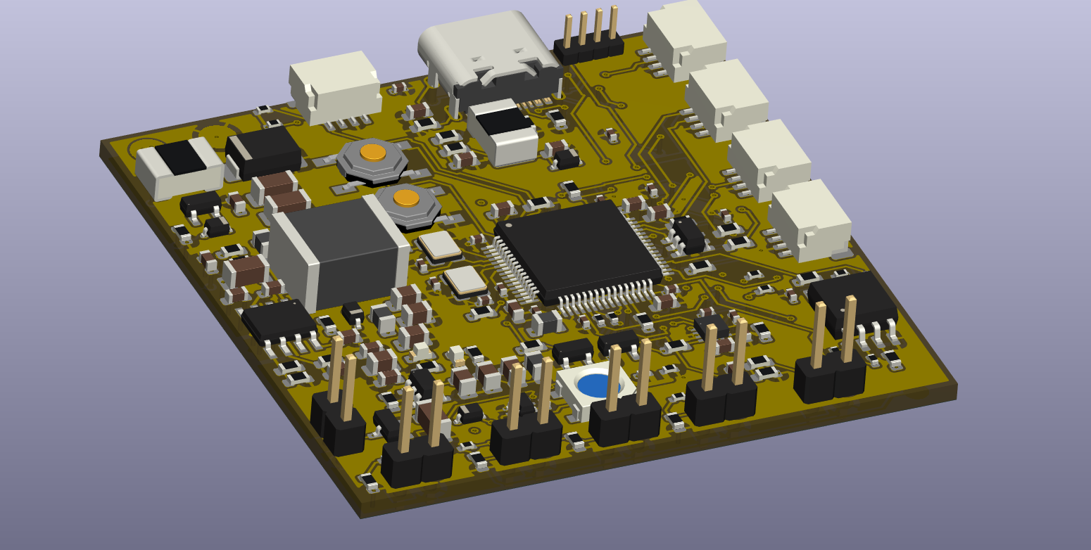
This flight controller is unique in a way, unlike most of the FC's which skip Fuses to save space, this contains 3 fuses, making the room for human errors tiny.
The main MCU is STM32F405RGT6, this tiny thing has 1MB flash and 192KB ram and can easily run betaflight at full speed. With betaflight it can also do blackbox (memory) logging, IMU (gyroscope) and OSD (share details like altitude etc) simultaneously.
IMU I used for this project is ICM-42688-P which runs at 24 MHZ! It's a 6 axis gyroscope. I chose this because it is low noise (doesn't give false readings due to electrical noise) and gives reading in high resolution.
Then comes the blackbox which logs the data which is useful when the drone crashes or something so it is easier for us to point out errors. The exact module is W25Q128JVS, ~4 minutes of 2 kHz blackbox logging, or ~30 minutes at 500 Hz.
Watchdog-safe boot BOOT0 pull-down (R21) + BOOT1 pull-down (R25) MCU always boots from flash unless user says so. Sometimes when drone crashes MCU might repeatedly boot into USB mode and face continuous resets, but this mechanism ensures that, this aint going to happen.
No OSD: OSD is a chip that transmits data like altitude etc into the video, but most of the modern day digital cameras have this inbuilt. So I removed it.
No barometer: Same as OSD, most modern day GPS have barometer built in so there is no need of one on board.
2S - 6S input power, max 28V. And over current protection in built.
Reverse polarity protection,due to a P-FET on board even if the user connects + and - in reverse, power ain't gonna reach other parts,it's gonna stop at the P-Fet thus protecting rest of the FC.
USB ORing protection, with schkotty diode it ensures that USB and battery power won't fight or push power back.
5 independent UARTs, enough for connections GPS, Camera, etc with one spare.
4 pins for motors, with current and voltage measurement with dividers (a divider is a junction of Resistors which steps down the voltage/current and MCU multiplies it with a specific number,here 11 to get voltage and current readings).
Addressable RGB LED and two onboard LEDs indicating 5V and 3.3V with buzzer connections headers for audible output.
What makes it unique ? I built this board such that it is easy to debug, yes no board can work perfectly first time, this instead of saving space, i tried to make it more debuggable by adding multiple Testpoints.
This FC contains minimal architecture (as i am a rookie), it does not contain in built barometer or OSD.
Flight_Controller
├── PCB
│   ├── FlightController_Drone.csv
│   ├── FlightController_Drone.kicad_pcb
│   ├── FlightController_Drone.kicad_pro
│   ├── FlightController_Drone.kicad_sch
│   └── gerbers.zip
├── README.md
└── images
    ├── DRAFT
    │   ├── S10_2.png
    │   ├── S11_2.png
    │   ├── S12_2.png
    │   ├── S13_2.png
    │   ├── S1_1.png
    │   ├── S2_1.png
    │   ├── S3_1.png
    │   ├── S4_2.png
    │   ├── S4_P.png
    │   ├── S5_2.png
    │   ├── S6_2.png
    │   ├── S7_2.png
    │   ├── S8_2.png
│ ├── S9_2.png| Reference | Qty | Value | Footprint | LCSC Part # | Rough Price (USD) |
|---|---|---|---|---|---|
| C1,C2,C3,C8 | 4 | 10 uF, 35V | C_1206_3216Metric | C31750 | ~0.12 |
| C4,C5,C9,C10 | 4 | 100 nF, 50V | C_0603_1608Metric | C14663 | ~0.008 |
| C6 | 1 | 100 nF, 25V | C_0603_1608Metric | C14663 | ~0.008 |
| C7 | 1 | 100 nF, 16V | C_0603_1608Metric | C14663 | ~0.008 |
| C11,C12 | 2 | 22 uF, 10V | C_0805_2012Metric | C45783 | ~0.10 |
| C13,C19,C24 | 3 | 100 nF, 10V | C_0603_1608Metric | C14663 | ~0.008 |
| C14 | 1 | 100 pF | C_0603_1608Metric | — | ~0.01 |
| C15 | 1 | 100 nF | C_0603_1608Metric | C14663 | ~0.008 |
| C16 | 1 | 10 nF | C_0603_1608Metric | — | ~0.01 |
| C17,C18 | 2 | 10 uF, 10V | C_0805_2012Metric | — | ~0.06 |
| C20,C22 | 2 | 10 uF, 6.3V | C_0805_2012Metric | — | ~0.06 |
| C21 | 1 | 100 nF, 6.3V | C_0805_2012Metric | C14663 | ~0.008 |
| C23 | 1 | JK-mSMD1206P050TF | C_0603_1608Metric | — | ~0.05 |
| C25,C26,C27,C28,C34,C37,C38,C39,C40,C51,C52,C53,C54 | 13 | 100 nF, 16V | C_0402_1005Metric | C1525 | ~0.005 |
| C29 | 1 | 10 uF, 10V | C_1206_3216Metric | — | ~0.08 |
| C35 | 1 | 2.2 uF, 6.3V | C_0603_1608Metric | — | ~0.02 |
| C36 | 1 | 10 nF, 16V | C_0402_1005Metric | — | ~0.01 |
| C41,C42,C55 | 3 | 4.7 uF, 6.3V | C_0603_1608Metric | — | ~0.03 |
| C43,C44 | 2 | 2.2 uF, 6.3V | C_0603_1608Metric | — | ~0.02 |
| C45 | 1 | 100 nF | C_0402_1005Metric | C1525 | ~0.005 |
| C46 | 1 | 1 uF | C_0603_1608Metric | — | ~0.02 |
| C47,C48 | 2 | 18 pF | C_0402_1005Metric | — | ~0.01 |
| C49,C50 | 2 | 12.5 pF | C_0402_1005Metric | — | ~0.01 |
| D1 | 1 | SMBJ28A | D_SMB | — | ~0.10 |
| D2 | 1 | BZT52C10 | D_SOD-323 | — | ~0.02 |
| D3,D4 | 2 | BAT54S | SOT-23 | C7420 | ~0.01 |
| D5 | 1 | LEDG | LED_0603 | — | ~0.02 |
| D6 | 1 | LEDB | LED_0603 | — | ~0.02 |
| D7,D10 | 2 | SS14 | D_SOD-323 | C2480 | ~0.009 |
| D8 | 1 | 1N4148W | D_SOD-323 | — | ~0.01 |
| D9 | 1 | WS2812B | LED_WS2812B | C114586 | ~0.10 |
| F1 | 1 | JK-mSMD1812P200TF | Fuse_1812 | — | ~0.10 |
| F2 | 1 | 500 mA | Fuse_1812 | — | ~0.08 |
| FB1,FB2,FB3 | 3 | BLM21PG601SN1D | L_0805 | C16904 | ~0.02 |
| FB4 | 1 | BLM18PG601SN1D | L_0805 | C16904 | ~0.02 |
| J1 | 1 | Conn_01x04_Pin | PinHeader_1.27mm | — | ~0.10 |
| J1A1 | 1 | BAT+ | TestPoint_Pad_D3.0mm | — | ~0.05 |
| J1B1 | 1 | BAT- | TestPoint_Pad_D3.0mm | — | ~0.05 |
| J2,J5,J6,J7,J8,J13 | 6 | Conn_01x02_Pin | PinHeader_2.54mm | — | ~0.03 |
| J3 | 1 | USB_C_Receptacle_USB2.0_16P | USB_C_16P | C2997432 | ~0.30 |
| J9,J10,J11,J12,J14 | 5 | Conn_01x04_Pin | JST_SH_1x04 | — | ~0.15 |
| L1 | 1 | SWPA6045S150MT | L_6.3x6.3 | — | ~0.20 |
| PAD1,PAD2 | 2 | TestPoint | TestPoint_Pad_D2.0mm | — | ~0.03 |
| Q1 | 1 | AO3401 | SOT-23 | C77949 | ~0.02 |
| Q2 | 1 | 2N7002 | SOT-23 | C8545 | ~0.015 |
| R1,R21,R22,R23,R24,R25,R32,R37,R38,R39,R44,R45,R46,R47 | 14 | 10k Ω | R_0603 | C25804 | ~0.001 |
| R2,R6,R7,R9,R18,R19 | 6 | 10 kΩ | R_0603 | C25804 | ~0.001 |
| R3,R4,R5,R11 | 4 | 1 kΩ | R_0603 | C21190 | ~0.003 |
| R8 | 1 | 1.91 kΩ | R_0603 | — | ~0.01 |
| R10 | 1 | 100 kΩ | R_0603 | — | ~0.002 |
| R12 | 1 | 100 kΩ | R_0603 | — | ~0.002 |
| R13 | 1 | 330 Ω | R_0603 | — | ~0.002 |
| R14,R15 | 2 | 5.1 kΩ | R_0603 | — | ~0.002 |
| R16,R17 | 2 | 22 Ω | R_0603 | — | ~0.002 |
| R20 | 1 | 1 MΩ | R_0603 | — | ~0.002 |
| R27,R28,R29,R30,R33,R34,R35,R36,R40,R41,R42,R43 | 12 | 33 Ω | R_0402 | — | ~0.002 |
| R31 | 1 | 33 Ω | R_0603 | — | ~0.002 |
| R48 | 1 | 1 kΩ | R_0402 | C21190 | ~0.003 |
| R49,R51 | 2 | 10 kΩ | R_0402 | C25804 | ~0.001 |
| R50 | 1 | 330 Ω | R_0402 | — | ~0.002 |
| R52,R53 | 2 | 4.7 kΩ | R_0402 | — | ~0.002 |
| SW1 | 1 | BOOT | SW_SPST_TL3342 | — | ~0.10 |
| SW2 | 1 | RESET | SW_SPST_TL3342 | — | ~0.10 |
| TP1,TP2,TP3,TP4,TP5,TP6,TP7,TP8 | 8 | TestPoint | TestPoint_Pad_D1.5mm | — | ~0.02 |
| U1 | 1 | TPS54336ADDA | SO-PowerPAD-8 | C1355769 | ~1.40 |
| U2 | 1 | LP5907MFX-3.3 | SOT-23-5 | — | ~0.30 |
| U3 | 1 | USBLC6-2SC6 | SOT-23-6 | C7519 | ~0.15 |
| U4 | 1 | STM32F405RGTx | LQFP-64 | C15742 | ~5.42 |
| U5 | 1 | ICM-42688-P | LGA14 | C1850416 | ~3.50 |
| U6 | 1 | W25Q128JVS | SOIC-8 | C97521 | ~0.80 |
| U7 | 1 | 74AHCT1G125 | SOT-353 | — | ~0.05 |
| Y1 | 1 | X32258MSB4SI | Crystal_SMD_3225 | — | ~0.30 |
| Y2 | 1 | X321532768KGD2SI | Crystal_SMD_3225 | — | ~0.20 |
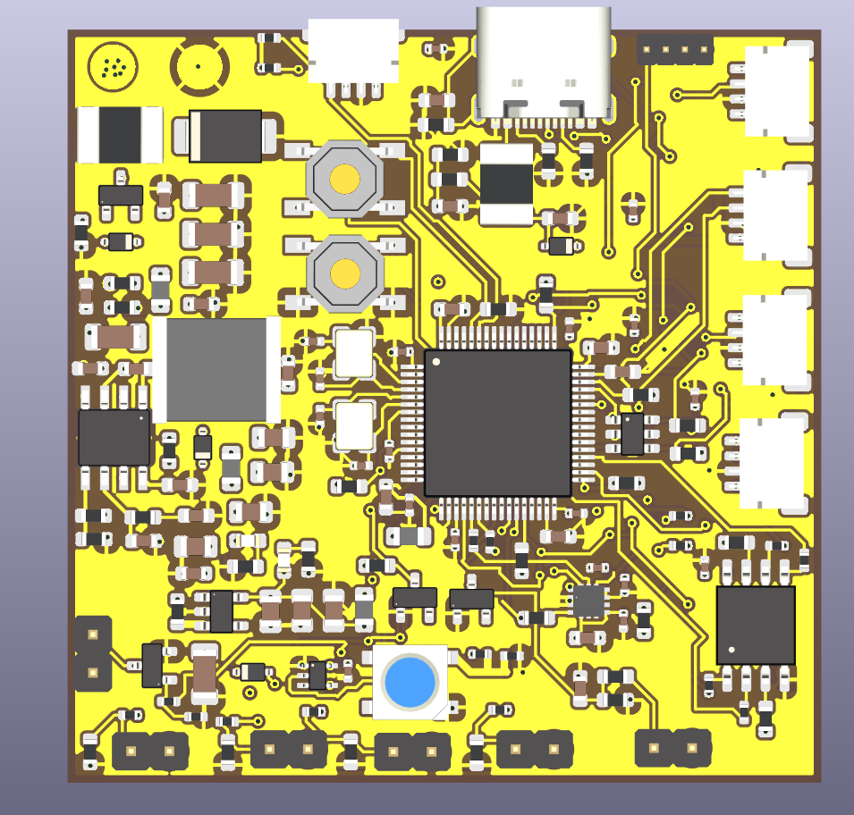
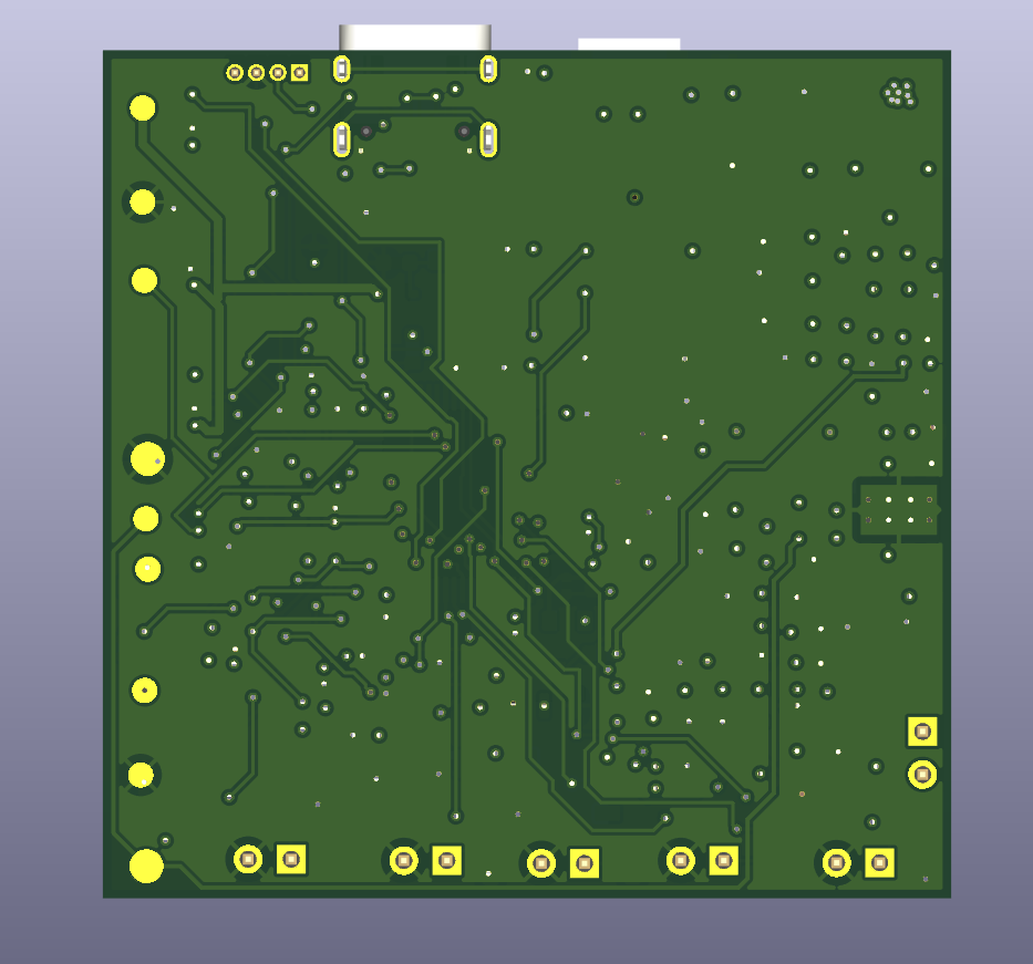
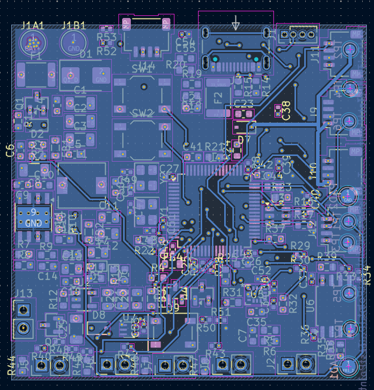
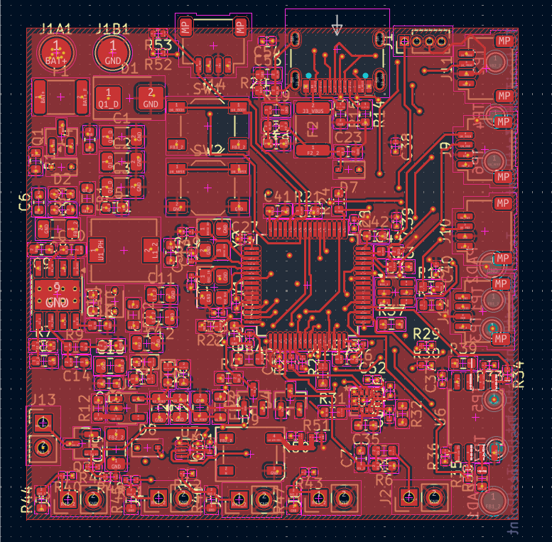
FOR MORE IMAGES PLEASE CHECK images FOLDER
DRC is giving weird errors about footprints touching each other which is fine until pads touch, so I moved them into warnings.
Ai was used only in one or two instances to verify netlist, this makes AI usage less than 5% for this project.
MIT License and you are free to manufacture this board (ik no one will) but in case it dont work, inform me :)
| Qty | Value | Footprint | References |
|---|---|---|---|
| 14 | 10k Ω | Resistor_SMD:R_0603_1608Metric | R1, R21, R22, R23, R24, R25, R32, R37, R38, R39, R44, R45, R46, R47 |
| 13 | 100 nF, 16V | Capacitor_SMD:C_0402_1005Metric | C25, C26, C27, C28, C34, C37, C38, C39, C40, C51, C52, C53, C54 |
| 12 | 33Ω | Resistor_SMD:R_0402_1005Metric | R27, R28, R29, R30, R33, R34, R35, R36, R40, R41, R42, R43 |
| 7 | TestPoint | TestPoint:TestPoint_Pad_D1.5mm | TP1, TP2, TP3, TP4, TP5, TP6, TP7 |
| 6 | 10 kΩ | Resistor_SMD:R_0603_1608Metric | R2, R6, R7, R9, R18, R19 |
| 6 | Conn_01x02_Pin | Connector_PinHeader_2.54mm:PinHeader_1x02_P2.54mm_Vertical | J2, J5, J6, J7, J8, J13 |
| 5 | Conn_01x04_Pin | Connector_JST:JST_SH_SM04B-SRSS-TB_1x04-1MP_P1.00mm_Horizontal | J9, J10, J11, J12, J14 |
| 4 | 1 kΩ | Resistor_SMD:R_0603_1608Metric | R3, R4, R5, R11 |
| 4 | 10 uF, 35V | Capacitor_SMD:C_1206_3216Metric | C1, C2, C3, C8 |
| 4 | 100 nF, 50V | Capacitor_SMD:C_0603_1608Metric | C4, C5, C9, C10 |
| 3 | 100 nF, 10V | Capacitor_SMD:C_0603_1608Metric | C13, C19, C24 |
| 3 | 4.7 uF, 6.3V | Capacitor_SMD:C_0603_1608Metric | C41, C42, C55 |
| 3 | BLM21PG601SN1D | Inductor_SMD:L_0805_2012Metric | FB1, FB2, FB3 |
| 2 | 10 kΩ | Resistor_SMD:R_0402_1005Metric | R49, R51 |
| 2 | 10 uF, 10V | Capacitor_SMD:C_0805_2012Metric | C17, C18 |
| 2 | 10 uF, 6.3V | Capacitor_SMD:C_0805_2012Metric | C20, C22 |
| 2 | 12.5 pF | Capacitor_SMD:C_0402_1005Metric | C49, C50 |
| 2 | 18 pF | Capacitor_SMD:C_0402_1005Metric | C47, C48 |
| 2 | 2.2 uF, 6.3V, ESR < 2Ω | Capacitor_SMD:C_0603_1608Metric | C43, C44 |
| 2 | 22 uF, 10V | Capacitor_SMD:C_0805_2012Metric | C11, C12 |
| 2 | 22Ω | Resistor_SMD:R_0603_1608Metric | R16, R17 |
| 2 | 4.7 kΩ | Resistor_SMD:R_0402_1005Metric | R52, R53 |
| 2 | 5.1 kΩ | Resistor_SMD:R_0603_1608Metric | R14, R15 |
| 2 | BAT54S | Package_TO_SOT_SMD:SOT-23 | D3, D4 |
| 2 | SS14 | Diode_SMD:D_SOD-323 | D7, D10 |
| 2 | TestPoint | TestPoint:TestPoint_Pad_D2.0mm | PAD1, PAD2 |
| 1 | 1 MΩ | Resistor_SMD:R_0603_1608Metric | R20 |
| 1 | 1 kΩ | Resistor_SMD:R_0402_1005Metric | R48 |
| 1 | 1 uF | Capacitor_SMD:C_0603_1608Metric | C46 |
| 1 | 1.91 kΩ | Resistor_SMD:R_0603_1608Metric | R8 |
| 1 | 10 nF | Capacitor_SMD:C_0603_1608Metric | C16 |
| 1 | 10 nF, 16V | Capacitor_SMD:C_0402_1005Metric | C36 |
| 1 | 10 uF, 10V | Capacitor_SMD:C_1206_3216Metric | C29 |
| 1 | 100 kΩ | Resistor_SMD:R_0603_1608Metric | R12 |
| 1 | 100 kΩ | Resistor_SMD:R_0603_1608Metric | R10 |
| 1 | 100 nF | Capacitor_SMD:C_0402_1005Metric | C45 |
| 1 | 100 nF | Capacitor_SMD:C_0603_1608Metric | C15 |
| 1 | 100 nF, 16V | Capacitor_SMD:C_0603_1608Metric | C7 |
| 1 | 100 nF, 25V | Capacitor_SMD:C_0603_1608Metric | C6 |
| 1 | 100 nF, 6.3V | Capacitor_SMD:C_0805_2012Metric | C21 |
| 1 | 100 pF | Capacitor_SMD:C_0603_1608Metric | C14 |
| 1 | 1N4148W | Diode_SMD:D_SOD-323 | D8 |
| 1 | 2.2 uF, 6.3V | Capacitor_SMD:C_0603_1608Metric | C35 |
| 1 | 2N7002 | Package_TO_SOT_SMD:SOT-23 | Q2 |
| 1 | 33 Ω | Resistor_SMD:R_0603_1608Metric | R31 |
| 1 | 330 Ω | Resistor_SMD:R_0603_1608Metric | R13 |
| 1 | 330 Ω | Resistor_SMD:R_0402_1005Metric | R50 |
| 1 | 500 mA | Fuse:Fuse_1812_4532Metric | F2 |
| 1 | 74AHCT1G125 | Package_TO_SOT_SMD:SOT-353_SC-70-5 | U7 |
| 1 | AO3401 | Package_TO_SOT_SMD:SOT-23 | Q1 |
| 1 | BAT+ | TestPoint:TestPoint_Pad_D3.0mm | J1A1 |
| 1 | BAT- | TestPoint:TestPoint_Pad_D3.0mm | J1B1 |
| 1 | BLM18PG601SN1D | Inductor_SMD:L_0805_2012Metric | FB4 |
| 1 | BOOT | Button_Switch_SMD:SW_SPST_TL3342 | SW1 |
| 1 | BZT52C10 | Diode_SMD:D_SOD-323 | D2 |
| 1 | Conn_01x04_Pin | Connector_PinHeader_1.27mm:PinHeader_1x04_P1.27mm_Vertical | J1 |
| 1 | ICM-42688-P | Custom_Footprints:LGA14_2P5X3X0P91_TDK | U5 |
| 1 | JK-mSMD1206P050TF | Capacitor_SMD:C_0603_1608Metric | C23 |
| 1 | JK-mSMD1812P200TF | Fuse:Fuse_1812_4532Metric | F1 |
| 1 | LEDB | LED_SMD:LED_0603_1608Metric | D6 |
| 1 | LEDG | LED_SMD:LED_0603_1608Metric | D5 |
| 1 | LP5907MFX-3.3 | Package_TO_SOT_SMD:SOT-23-5 | U2 |
| 1 | RESET | Button_Switch_SMD:SW_SPST_TL3342 | SW2 |
| 1 | SMBJ28A | Diode_SMD:D_SMB | D1 |
| 1 | STM32F405RGTx | Package_QFP:LQFP-64_10x10mm_P0.5mm | U4 |
| 1 | SWPA6045S150MT | Inductor_SMD:L_6.3x6.3_H3 | L1 |
| 1 | TPS54336ADDA | Package_SO:TI_SO-PowerPAD-8_ThermalVias | U1 |
| 1 | USBLC6-2SC6 | Package_TO_SOT_SMD:SOT-23-6 | U3 |
| 1 | USB_C_Receptacle_USB2.0_16P | Connector_USB:USB_C_Receptacle_HCTL_HC-TYPE-C-16P-01A | J3 |
| 1 | W25Q128JVS | Package_SO:SOIC-8_5.3x5.3mm_P1.27mm | U6 |
| 1 | WS2812B | LED_SMD:LED_WS2812B_PLCC4_5.0x5.0mm_P3.2mm | D9 |
| 1 | X321532768KGD2SI | Crystal:Crystal_SMD_3225-4Pin_3.2x2.5mm | Y2 |
| 1 | X32258MSB4SI | Crystal:Crystal_SMD_3225-4Pin_3.2x2.5mm | Y1 |
It measures 50 × 50 mm and has 4 copper layers, 1.56 mm thick.
157 parts, built around the 74AHCT1G125SE, TPS54336ADDA, W25Q128JVSIQ and ICM-42688-P. The full list of its parts is on this page, with links to each part's symbol and footprint where PCBKit's library has them.
From the damnitzhemanth-oss/Flight_Controller repository on GitHub, at the commit this page was made from: the board is PCB/FlightController_Drone.kicad_pcb and its schematic PCB/FlightController_Drone.kicad_sch. PCBKit opens the board in the browser, with nothing to install.
Its repository states no licence, so its author keeps all rights: ask damnitzhemanth-oss before reusing the design.
sbbxiii/The-Eagle
The Eagle: Custom STM32F405 4-Layer Autonomous Avionics Flight Controller PCB


jdg511/567Terror
Software simulation of the Glitchwave 567 (LM567 glitch pedal) — JUCE Standalone + VST3


lmiez/yecnodF405
Open source flight controller based on the STM32F405 MCU that runs betaflight.
