2 layers53.3 × 68.6 mm

 sLeon2005/Team-ATOLE-Manufacturing-Cell
End-to-end Industry 4.0 manufacturing system featuring industrial automation, machine vision, collaborative robotics, IIoT monitoring, cybersecurity, and digital manufacturing.
RfidRelayInterfacePCB is an open-source printed circuit board by sLeon2005, from the sLeon2005/Team-ATOLE-Manufacturing-Cell repository on GitHub, published under the MIT licence. It is a 2-layer board of 96.5 × 96.5 mm with 88 parts on 65 nets, routed with 339 tracks and 127 vias.
It is built around the ATMEGA328-PU, CH340C and AMS1117-3.3, with the IRLML2502 and SS34 among its other parts. Its parts include 22 resistors, 12 capacitors, 7 switches, 6 diodes and 5 connectors. It belongs with the robots and motor control and home automation and IoT boards and the ESP32 and AVR (ATmega, ATtiny) boards of this library.


An Industry 4.0 manufacturing cell developed at Tecnológico de Monterrey that integrates industrial automation, machine vision, collaborative robotics, Industrial IoT, cybersecurity, custom electronics, and digital manufacturing.
The system simulates an automated pastry production facility capable of:
The project combines machining, industrial automation, robotics, cybersecurity, and Industrial IoT into a single integrated manufacturing system.
The complete solution is divided into two major subsystems:
A custom Aluminum 6061 workpiece was designed, manufactured, and monitored during machining operations.
A custom non-invasive monitoring system measures:
The collected data is transmitted through MQTT and visualized in real time using a Node-RED dashboard.

The manufacturing cell is controlled by two Siemens S7-1200 PLCs interconnected through industrial Ethernet communication.
The production process includes:


The architecture integrates:
The automation layer was implemented using two Siemens S7-1200 PLCs communicating through an S7 network.
Key features include:

A Cognex industrial vision sensor acts as the cell’s quality gate.
Three reference objects are classified and mapped to production recipes:
| Object | Recipe |
|---|---|
| Turned Aluminum Part | Chocolate |
| Milled Aluminum Part | Strawberry |
| Metal Hook | Vanilla |
The detected classification is transmitted directly to the PLC network and automatically configures downstream process parameters.

A UFACTORY xArm Lite 6 collaborative robot performs:
The robot was programmed in Python using the xArm SDK and operates through a Finite State Machine (FSM) architecture capable of managing multiple workpieces simultaneously.

A custom monitoring cabinet was developed around:
The system continuously estimates:
without requiring direct electrical connection to the machine power circuit.

Process variables are published through MQTT and visualized through a Node-RED dashboard.
Available metrics include:

An RFID authentication system was integrated to restrict access to critical HMI functions.
Only authorized operators are allowed to access or modify manufacturing parameters.

Several custom-designed hardware components were developed specifically for this project.
Custom PCB for:

Several custom electronic and mechanical systems were designed and fabricated specifically for this project.
A custom PCB based on the ATmega328P was designed to provide RFID-based operator authentication.
Main features:
The board allows the PLC to identify authorized operators and restrict access to critical manufacturing functions.
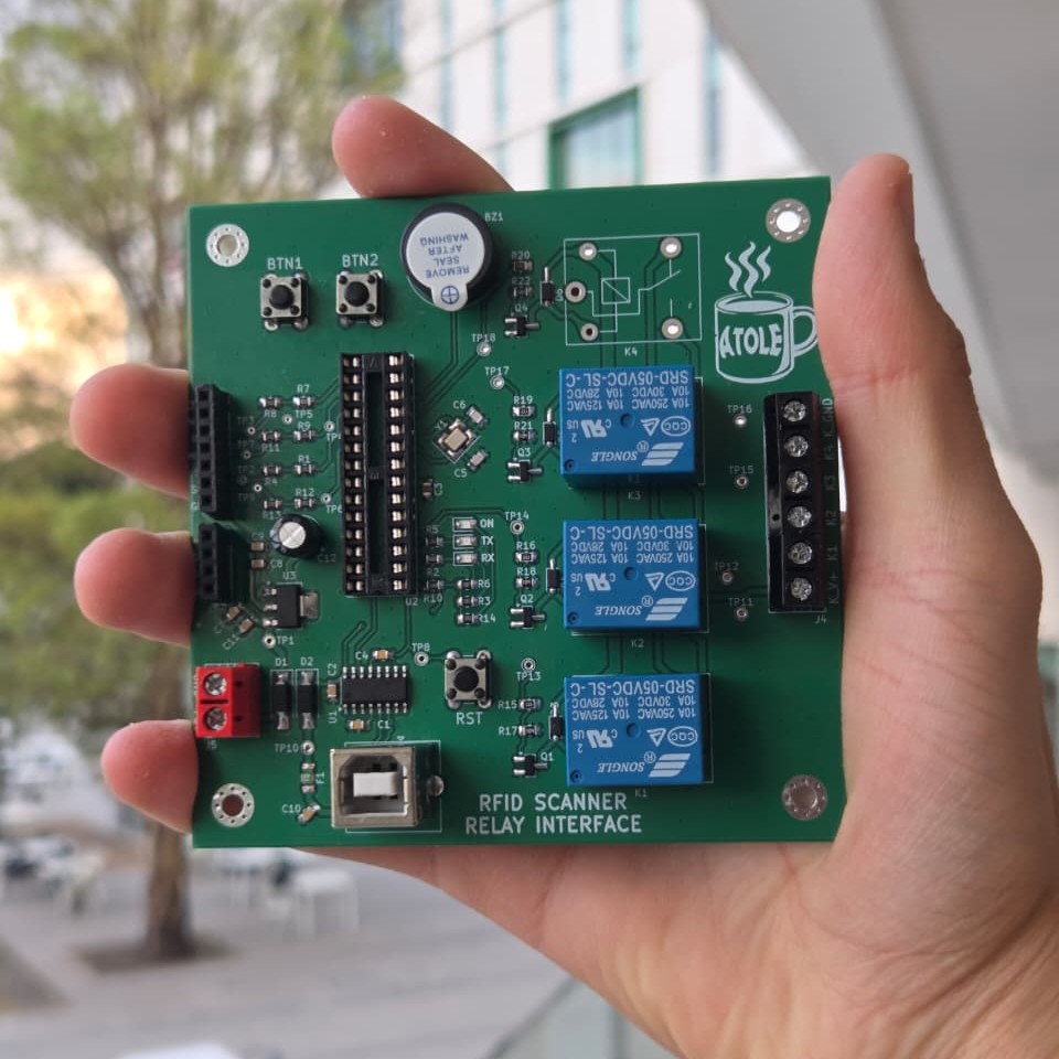
A dedicated Industrial IoT monitoring system was developed to analyze the electrical consumption of the ROMI T240 lathe.
Hardware used:
The system was implemented on a prototyping board and publishes real-time data through MQTT for remote monitoring and energy analysis.

Custom grippers were designed and manufactured to handle:

A stepped Aluminum 6061 workpiece was designed in Fusion 360 and manufactured on a ROMI T240 lathe.
The part serves both as a manufactured component and as a reference object for the vision classification system.
| CAD Model | Manufactured Part |
|---|---|
 |  |
The final system successfully demonstrated:
✅ Industrial machine vision integration
✅ Dual-PLC communication architecture
✅ Collaborative robotic manipulation
✅ Automated product assembly
✅ Automated palletizing
✅ MQTT-based Industrial IoT monitoring
✅ Real-time energy analytics
✅ RFID-based cybersecurity controls
✅ Custom electronics and PCB development
✅ End-to-end Industry 4.0 integration
Team ATOLE
Tecnológico de Monterrey, Campus Querétaro
B.S. in Mechatronics Engineering
This project is licensed under the MIT License.
| Qty | Value | Footprint | References |
|---|---|---|---|
| 11 | TestPoint | TestPoint:TestPoint_THTPad_D1.5mm_Drill0.7mm | TP1, TP8, TP10, TP11, TP12, TP13, TP14, TP15, TP16, TP17, TP18 |
| 9 | 1K | Resistor_SMD:R_0805_2012Metric_Pad1.20x1.40mm_HandSolder | R1, R2, R3, R5, R6, R7, R9, R12, R14 |
| 8 | 100nF | Capacitor_SMD:C_0805_2012Metric_Pad1.18x1.45mm_HandSolder | C1, C2, C4, C7, C8, C9, C10, C11 |
| 7 | TestPoint | TestPoint:TestPoint_THTPad_D1.0mm_Drill0.5mm | TP2, TP3, TP4, TP5, TP6, TP7, TP9 |
| 4 | 100K | Resistor_SMD:R_0805_2012Metric_Pad1.20x1.40mm_HandSolder | R17, R18, R21, R22 |
| 4 | 1N5819 | Diode_SMD:D_SOD-323_HandSoldering | D3, D4, D5, D6 |
| 4 | 220R | Resistor_SMD:R_0805_2012Metric_Pad1.20x1.40mm_HandSolder | R15, R16, R19, R20 |
| 4 | 2K | Resistor_SMD:R_0805_2012Metric_Pad1.20x1.40mm_HandSolder | R4, R8, R11, R13 |
| 4 | IRLML2502 | Package_TO_SOT_SMD:SOT-23_Handsoldering | Q1, Q2, Q3, Q4 |
| 4 | MountingHole | MountingHole:MountingHole_3.2mm_M3_Pad_Via | H2, H3, H4, H5 |
| 4 | SANYOU_SRD_Form_C | Relay_THT:Relay_SPDT_SANYOU_SRD_Series_Form_C | K1, K2, K3, K4 |
| 3 | SW_Push | Button_Switch_THT:SW_PUSH_6mm_H5mm | SW1, SW2, SW3 |
| 3 | ~ | LED_SMD:LED_0805_2012Metric_Pad1.15x1.40mm_HandSolder | ON1, RX1, TX1 |
| 2 | 22pF | Capacitor_SMD:C_0805_2012Metric_Pad1.18x1.45mm_HandSolder | C5, C6 |
| 2 | SS34 | Diode_SMD:D_SMA_Handsoldering | D1, D2 |
| 1 | 100uF | Capacitor_THT:CP_Radial_D6.3mm_P2.50mm | C12 |
| 1 | 10K | Resistor_SMD:R_0805_2012Metric_Pad1.20x1.40mm_HandSolder | R10 |
| 1 | 10uF | Capacitor_SMD:C_0805_2012Metric_Pad1.18x1.45mm_HandSolder | C3 |
| 1 | 16MHz | Crystal:Crystal_SMD_3225-4Pin_3.2x2.5mm_HandSoldering | Y1 |
| 1 | AMS1117-3.3 | Package_TO_SOT_SMD:SOT-223-3_TabPin2 | U3 |
| 1 | ATmega328-P | Package_DIP:DIP-28_W7.62mm_Socket_LongPads | U2 |
| 1 | Buzzer | Buzzer_Beeper:Buzzer_D14mm_H7mm_P10mm | BZ1 |
| 1 | CH340C | Package_SO:SOIC-16_3.9x9.9mm_P1.27mm | U1 |
| 1 | Conn_01x04_Socket | Connector_PinHeader_2.54mm:PinHeader_1x04_P2.54mm_Vertical | J3 |
| 1 | Conn_01x07_Pin | Connector_PinSocket_2.54mm:PinSocket_1x07_P2.54mm_Vertical | J2 |
| 1 | Fuse | Fuse:Fuse_1206_3216Metric_Pad1.42x1.75mm_HandSolder | F1 |
| 1 | LOGO | LOGO | G*** |
| 1 | Screw_Terminal_01x02 | TerminalBlock:TerminalBlock_MaiXu_MX126-5.0-02P_1x02_P5.00mm | J5 |
| 1 | Screw_Terminal_01x06 | TerminalBlock:TerminalBlock_MaiXu_MX126-5.0-06P_1x06_P5.00mm | J4 |
| 1 | USB_B | Connector_USB:USB_B_TE_5787834_Vertical | J1 |


shazmeenShz/ESP32-Flight-Controller
Custom 4-layer IoT-Ready ESP32 Flight Controller PCB designed in KiCad 8 featuring USB Type-C, CH340C, MP1584 power management, MPU6050 interface, and manufacturing-ready Gerber files.


nsm81/VehicleVCU_PCB
A Vehicle Control Unit provides multiple CANBUS transceivers for communication within a vehicle.


It measures 96.5 × 96.5 mm and has 2 copper layers, 1.6 mm thick.
88 parts, built around the ATMEGA328-PU, CH340C, AMS1117-3.3 and IRLML2502. The full list of its parts is on this page, with links to each part's symbol and footprint where PCBKit's library has them.
From the sLeon2005/Team-ATOLE-Manufacturing-Cell repository on GitHub, at the commit this page was made from: the board is RFID-Relay-Interface/rfidRelayInterfacePCB/rfidRelayInterfacePCB.kicad_pcb and its schematic RFID-Relay-Interface/rfidRelayInterfacePCB/relays.kicad_sch. PCBKit opens the board in the browser, with nothing to install.
Its repository publishes it under the MIT licence: you may reuse it on that licence's terms (keep the author's notice, and for a copyleft licence share your changes alike).