Skip to the content
2 layers85 × 56 mmHB RF ETH, the printed circuit board in 3D

Some of my PCBs

Size
85 × 56 mm
Copper layers
2
Thickness
1.6 mm
Parts
96
Nets
110
Pads
361
Tracks, vias
1,326, 97
Pours
4
Routed
Yes
KiCad
KiCad 5 (file 20171130)
Created
23 Apr 2018
Updated
30 Mar 2026

Overview

HB RF ETH is an open-source printed circuit board by alexreinert, from the alexreinert/PCB repository on GitHub. It is a 2-layer board of 85 × 56 mm with 96 parts on 110 nets, routed with 1,326 tracks and 97 vias.

It is built around the CH340C, ESP32-WROOM-32 and AMS1117-3.3, with the LAN8720A-CP, SRV05-4 and S8050 among its other parts. Its parts include 35 resistors, 26 capacitors, 6 ICs, 6 transistors and 5 connectors. It belongs with the radio and wireless boards and the ESP32 boards of this library.

Main components

10

README

README.md

Creative Commons Lizenzvertrag

Dieses Werk ist lizenziert unter einer Creative Commons Namensnennung - Nicht-kommerziell - Weitergabe unter gleichen Bedingungen 4.0 International Lizenz.

Bei Nutzung der Platinen freue ich mich über Feedback und kleine Aufmerksamkeiten aus meiner Amazon Wunschliste.

Viele Platinen gibt es auch im offiziellen Shop viopcb.

PCB

HB-RF-ETH

Eine Platine um die Homematic Funkmodule HM-MOD-RPI-PCB und RPI-RF-MOD per Netzwerk anschließen zu können. Layout Schaltplan Die Platine benötigt spezielle Treiber, welche in debmatic und in piVCCU3 verfügbar sind. Eine passende Firmware findet sich unter HB-RF-ETH. Diese Platine ist auch als fertig bestückter Bausatz erhältlich bei viopcb.
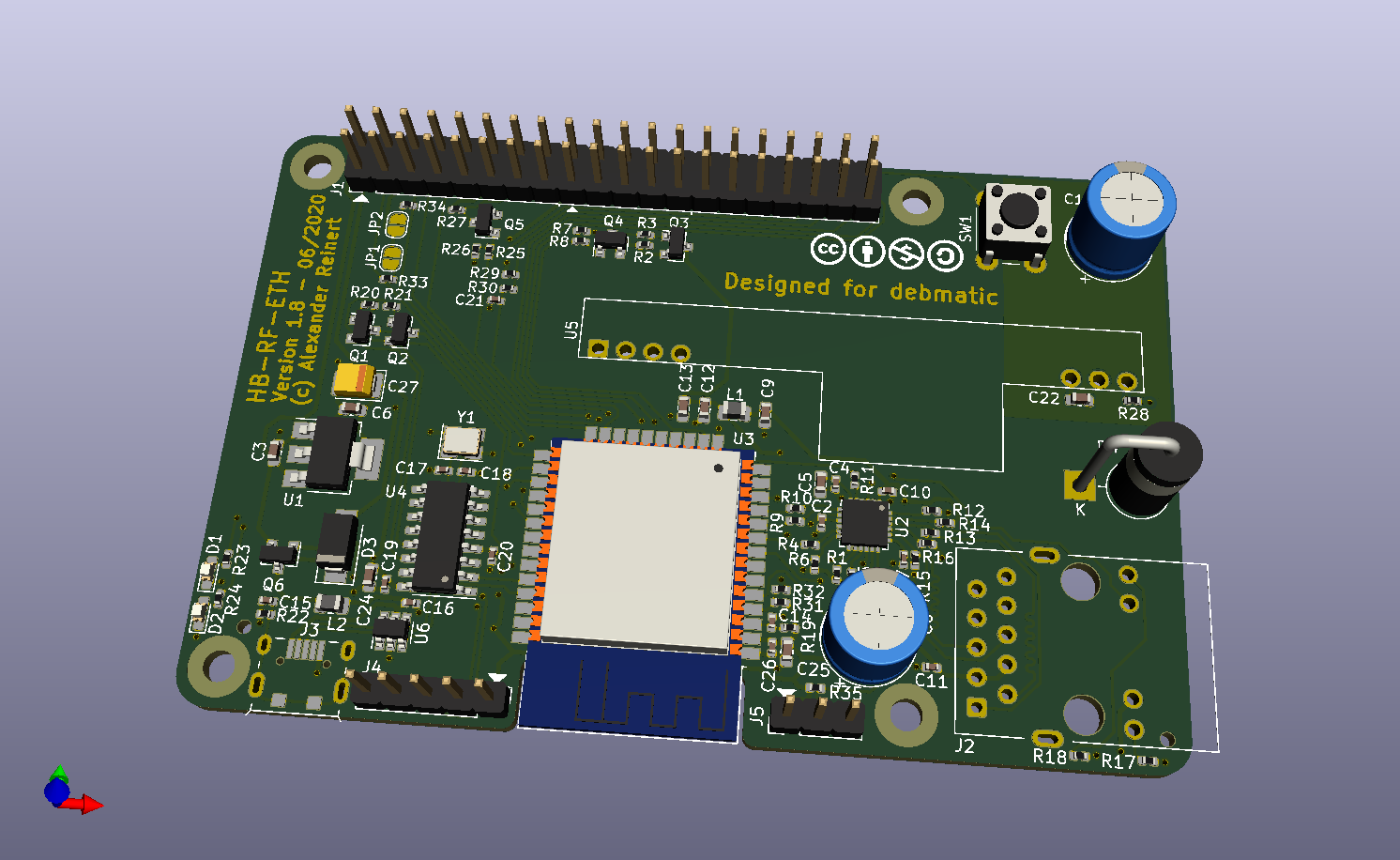
Benötigte Bauteile:

Siehe Schaltplan

HB-RF-USB-2

Eine Platine um die Homematic Funkmodule HM-MOD-RPI-PCB und RPI-RF-MOD per USB anschließen zu können. Layout Schaltplan Die Platine benötigt spezielle Treiber, diese sind in debmatic ab Version 3.51.6-45 und in piVCCU3 ab Version 3.51.6-40 eingebaut. Diese Platine ist auch als fertig bestückter Bausatz erhältlich bei viopcb.
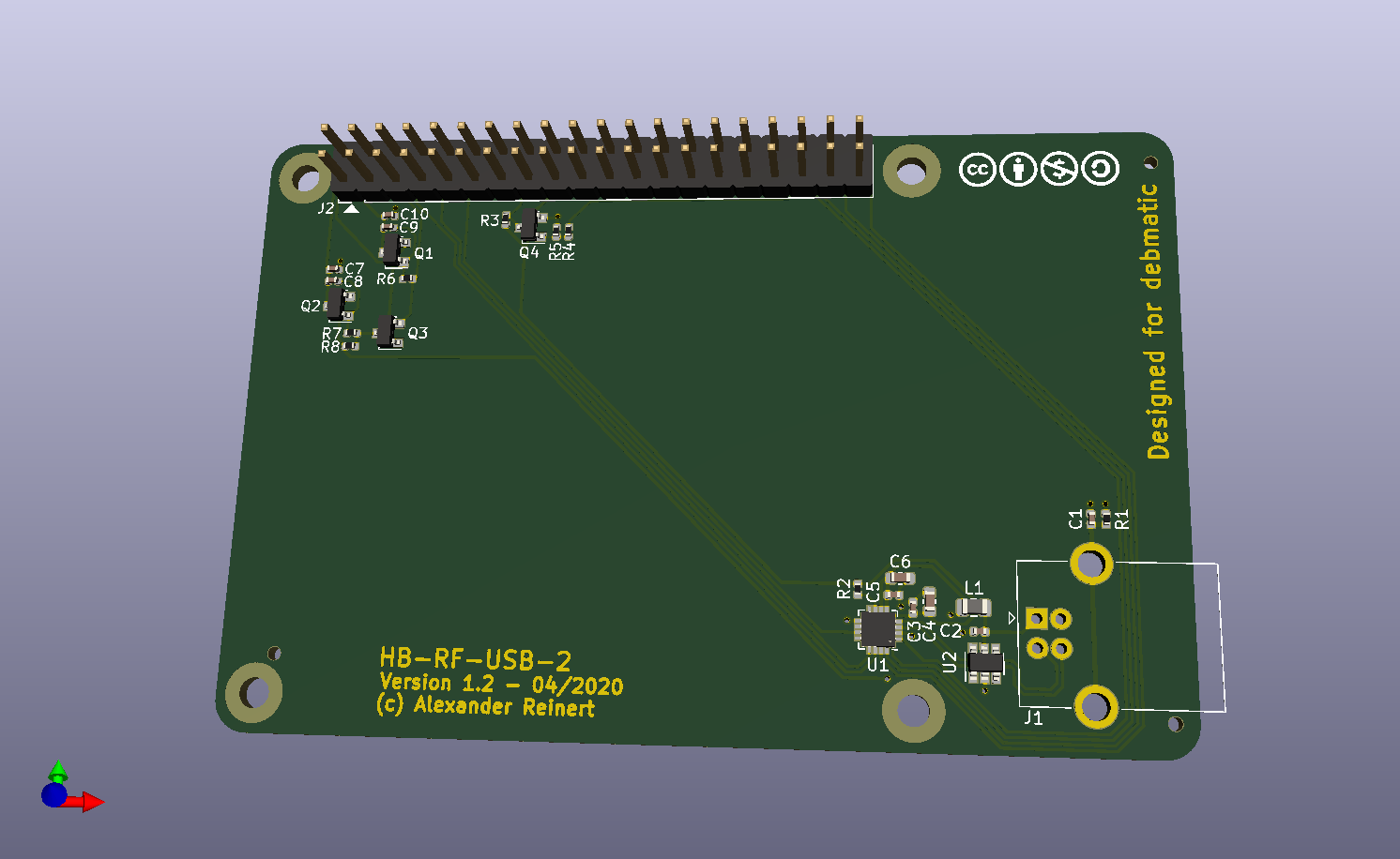
Benötigte Bauteile:

  • 1x CP2102N (U1)
  • 1x SRV05-4 (U2)
  • 2x Kerko 10nF 0402 (C1, C2)
  • 6x Kerko 100nF 0402 (C3, C5, C7, C8, C9, C10)
  • 2x Kerko 4.7uF 0603 (C4, C6)
  • 1x Ferrite Bead 100Ohm, 800mA 0805 (L1)
  • 2x AO3401A (Q1, Q2)
  • 1x AO3400A (Q3)
  • 1x S8050 (Q4)
  • 1x Widerstand 1M 0402 (R1)
  • 3x Widerstand 1K 0402 (R2, R6, R7)
  • 4x Widerstand 10K 0402 (R3, R4, R5, R8)
  • 1x USB B Buchse B1HSW6 (J1)
  • 1x Pinheader 2x20 (J2)

EEPROM flashen

Anleitung

HB-RF-USB

Eine Platine um die Homematic Funkmodule HM-MOD-RPI-PCB und RPI-RF-MOD per USB anschließen zu können. Layout Schaltplan Die Platine benötigt spezielle Treiber, diese sind in piVCCU3 ab Version 3.41.11-13, in debmatic und in RaspberryMatic ab Version 3.41.11.20190126 eingebaut. Diese Platine ist auch erhältlich bei viopcb
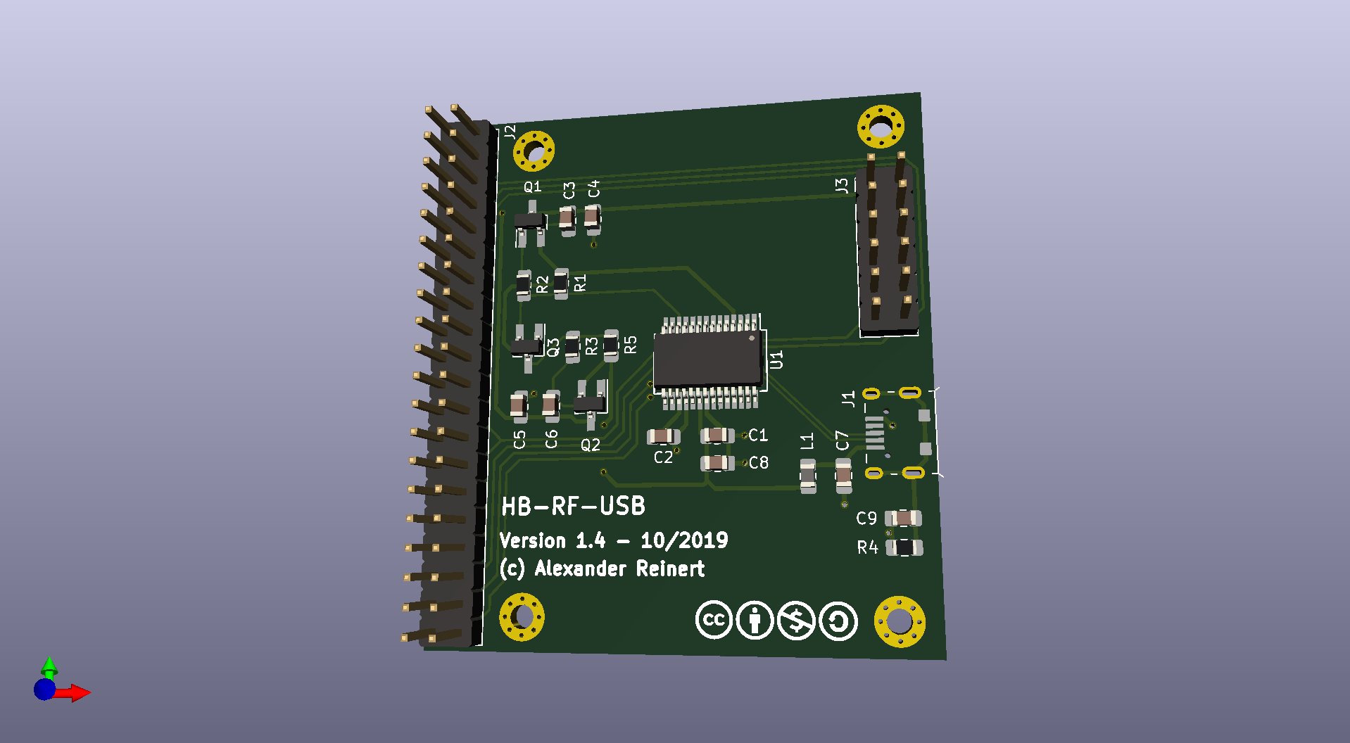
Benötigte Bauteile:

  • 1x FTDI FT232RL (U1)
  • 1x Micro USB Connector U-F-M5DD-Y-1 (bis Rev. 1.3 MK5P Micro USB Connector)
  • 1x Kerko 4.7nF 0805 (C9)
  • 1x Kerko 10nF 0805 (C7)
  • 6x Kerko 100nF 0805 (C1-C6)
  • 1x Kerko 4.7uF 0805 (C8)
  • 2x Widerstand 1K 0805 (R2, R3)
  • 2x Widerstand 10K 0805 (R1, R5)
  • 1x Widerstand 1M 0805 (R4)
  • 1x Ferritperle 30 Ohm 0805 (L1)
  • 2x IRLML6402 (Q1, Q2)
  • 1x IRLML2502 (Q3)
  • 1x Pinheader 2*6
  • 1x Pinheader 2*20

EEPROM flashen

Anleitung

HB-UNI-SEN-BATT

Eine universelle Platine für Homebrew Geräte basierend auf AskSin++ Library Layout Schaltplan Diese Platine ist auch erhältlich bei viopcb.
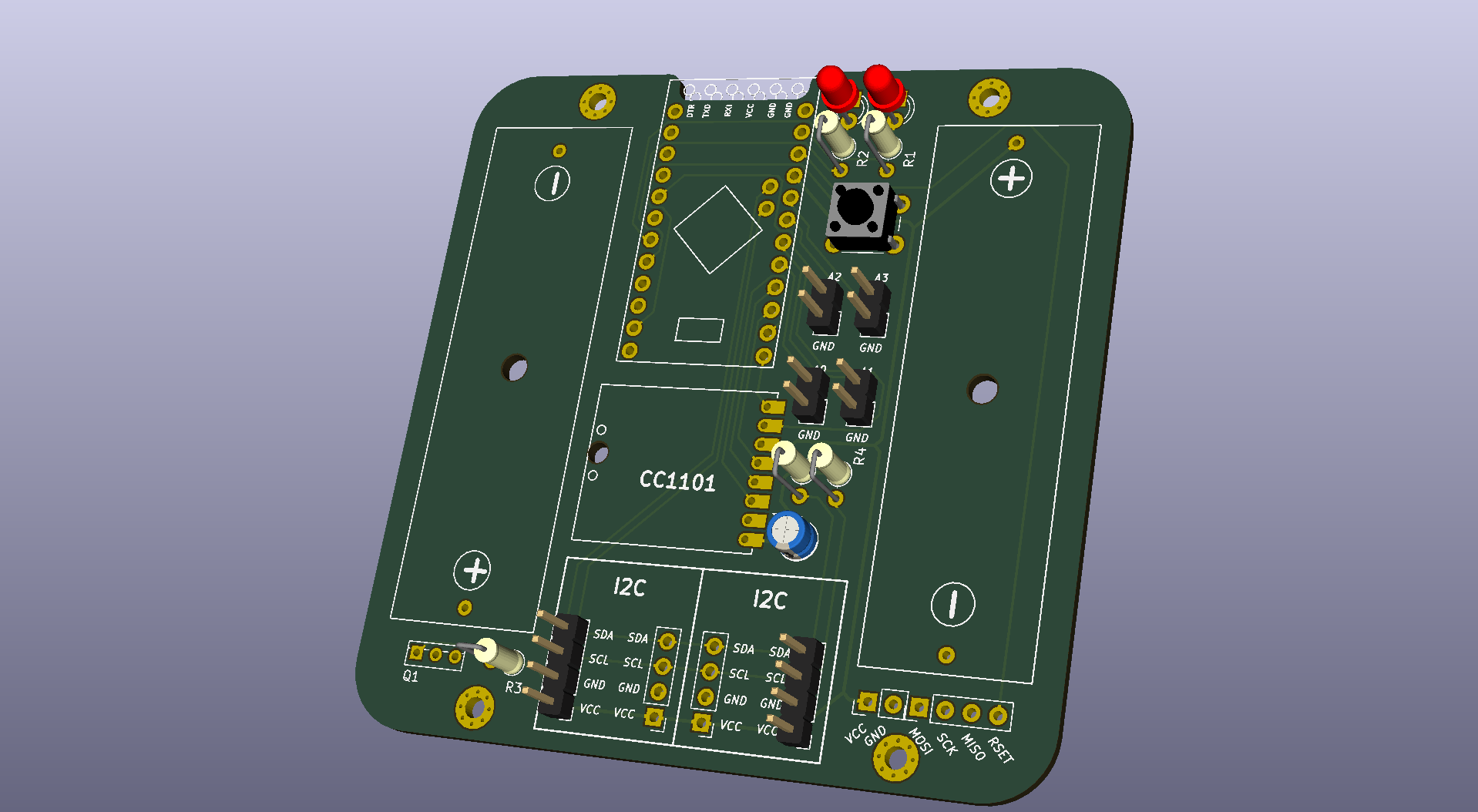
Benötigte Bauteile:

  • Arduino Pro Mini 3.3V 8Mhz (The Simple)
  • CC1101 Modulplatine 868MHz
  • 2x LEDs 3mm Low Current (Pin 4 und 5)
  • 2x 470Ohm Widerstände (Vorwiderstand für LEDs)
  • Elko 10uF 1,5mm
  • 2x Goobay Batteriehalter Mignon Print
  • Mikroschalter 6*6mm
  • Stiftleiste RM 2mm 1x8 Pin (Für CC1101)
  • Stiftleiste RM 2,54MM (nach Bedarf)
  • IRLU024N (optional für Verpolungsschutz)
  • 100KOhm Widerstand (optional für Verpolungsschutz)
  • 2x 10KOhm Widerstand (optional Pullup für I2C)

Passendes Gehäuse

  • Camdenboss CBRS01SWH und CBRS01VWH

Hinweise

  • Achtung: Kein Überspannungschutz vorhanden
  • Der Verpolungsschutz ist optional. Dafür Bauteil Q1 (IRLU024N) und R3 (100KOhm Widerstand) bestücken. Alternativ J8 auf der Platinenrückseite brücken um ohne Verpolungsschutz zu arbeiten.

HB-UNI-SEN-PCB

Eine universelle Platine für Homebrew Geräte basierend auf AskSin++ Library Layout Schaltplan Diese Platine ist auch erhältlich bei viopcb.
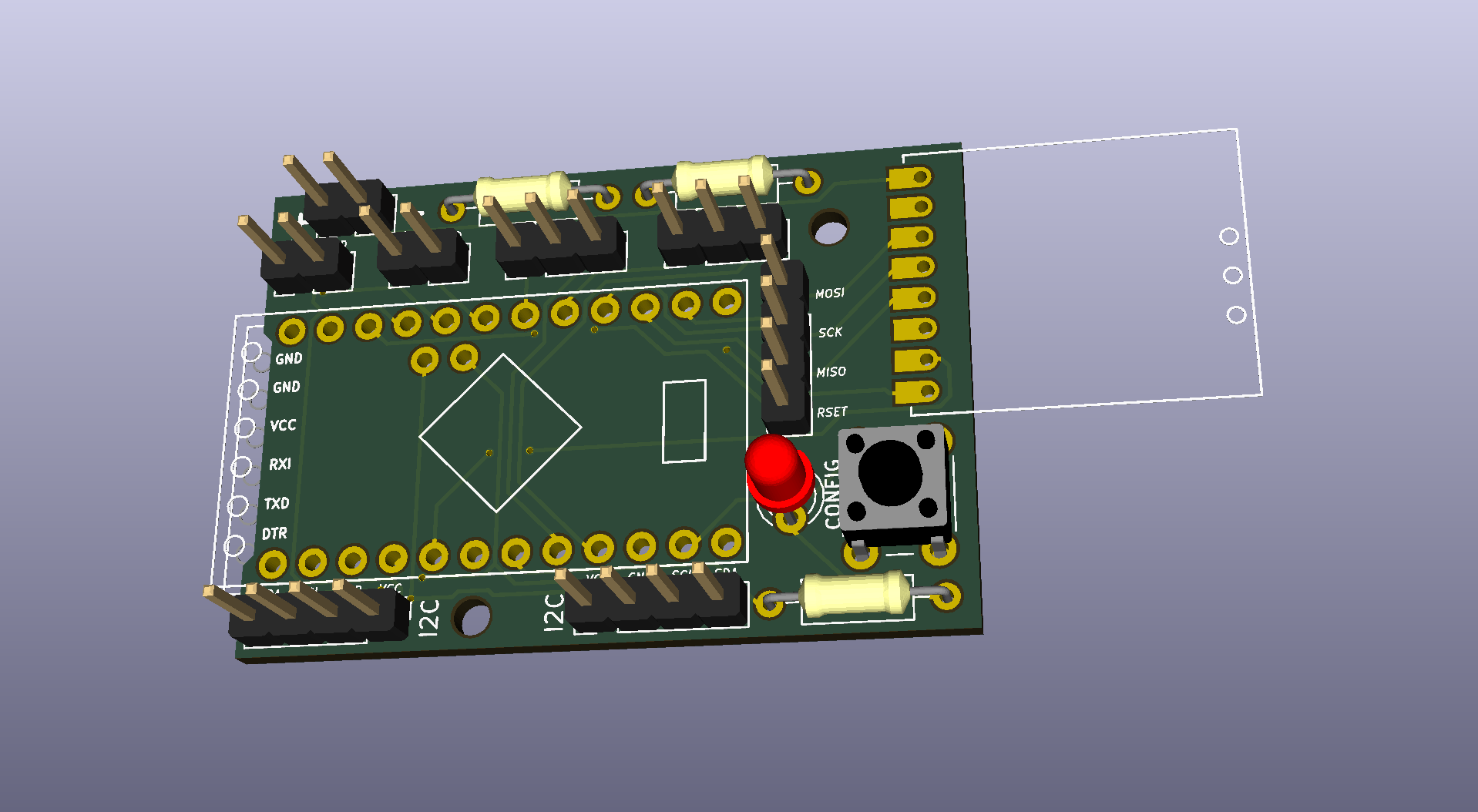
Benötigte Bauteile:

  • Arduino Pro Mini 3.3V 8Mhz (The Simple)
  • CC1101 Modulplatine 868MHz
  • 1x LEDs 3mm Low Current (Pin 4)
  • 1x 470Ohm Widerstände (Vorwiderstand für LEDs)
  • Mikroschalter 6*6mm
  • Stiftleiste RM 2mm 1x8 Pin (Für CC1101)
  • Stiftleiste RM 2,54MM (nach Bedarf)
  • Optional: 2x 10KOhm Widerstand und 2x 10KOhm PTC (Temperaturmessung mit PTC an A0 und A1)

Hinweise

  • Achtung: kein Verpolungs- oder Überspannungschutz vorhanden
  • Am I2C sind keine Pullups vorhanden, da diese im Regelfall auf I2C Platinen bereits integriert sind
  • Aktuell fehlt noch ein Kondensator am VCC vom CC1101.

HB-UNI-644 (Rev. 2)

Eine universelle Platine für Homebrew Geräte basierend auf AskSin++ Library und dem ATmega644PA Layout Schaltplan Diese Platine ist auch erhältlich bei viopcb.
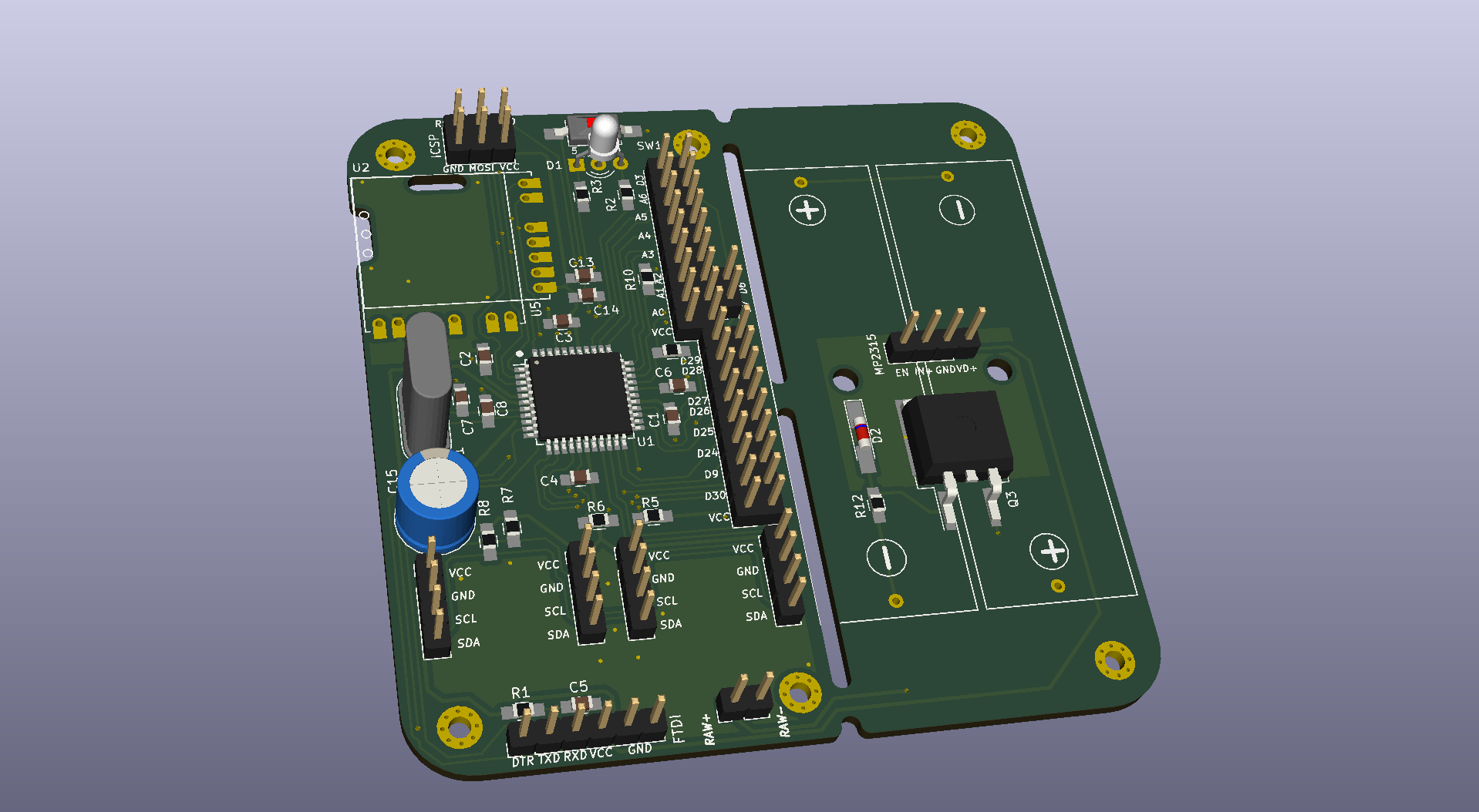
Benötigte Bauteile:

Grundfunktion
  • ATmega644PA oder ATmega1284P (TQFP44) (U1)
  • CC1101 Modulplatine 868MHz ggf. mit RM 2.0 Pinheader (U2)
  • 1x Kerko 10uF 0805 (C13)
  • 7x Kerko 100nF 0805 (C1-C6, C14)
  • 2x Widerstand 330 Ohm 0805 (R2, R3)
  • 1x Widerstand 10K Ohm 0805 (R1)
  • 1x Triple Color LED Common Cathode THT (D1)
  • 1x Tactile Switch 2 Pin 6x3.5 SMD (SW1)
  • 1x Quarz 8 Mhz HC49 THT (Y1) (optional)
  • 2x Kerko 22pF 0805 (C7, C8) (optional für Quarz)
  • Pinheader nach Bedarf
Power Option 1: Batteriebetrieb mit Step-Up
  • 2x Goobay Batteriehalter Mignon Print
  • 1x Widerstand 470K Ohm 0805 (R5)
  • 1x Widerstand 100K Ohm 0805 (R6)
  • 1x MAX1724EZK33 (U3)
  • 1x LQH43CN100K03L (L1)
  • 1x Kerko 10uF 0805 (C9)
  • 1x Kerko 33uF 1206 (C10)
Verpolungsschutz und Überlastschutz
  • 1x IRLML6244 (Q1)
  • 1x Widerstand 100K Ohm 0805 (R4)
  • 1x PTC 6V/250mA 1206 (F1)
Power Option 2: Externe Stromversorgung mit 5-9V, 100mA
  • 1x HT-7533-1 (U4)
  • 1x Kerko 10uF 50V 1206 (C11)
  • 1x Kerko 10uF 0805 (C12)
  • 1x Elko 1000uF 8mm*12mm (C15)
Verpolungsschutz und Überlastschutz
  • 1x IRLML5203 (Q2)
  • 1x Widerstand 100K Ohm 0805 (R11)
  • 1x PTC 16V/250mA 1206 (F1)
Power Option 3: Externe Stromversorgung 5-24V, 1A
  • 1x MP2315 Power Module Kontakt zum Trimmer durchtrennen, Lötbrücke bei 3.3V anbringen
  • 1x Elko 1000uF 8mm*12mm (C15)
Verpolungsschutz und Überlastschutz
  • 1x IRF4905S (Q3)
  • 1x Widerstand 100K Ohm 0805 (R12)
  • 1x Zener 16V MiniMelf (D2)
  • 1x PTC 30V/2A 1206 (F1)
I2C Pullup Widerstände (optional)
  • 2x Widerstand 10k Ohm 0805 (R7, R8)
Vorwiderstände für NTC Messung an A0 und A1
  • 2x Widerstand 10k Ohm 0805 (R9, R10)

Passendes Gehäuse

  • Camdenboss CBRS01SWH und CBRS01VWH

Betrieb mit 5V, 16MHz bei Netzbetrieb

  • Der MC kann auch mit 5V und dann mit 16MHz betrieben werden, dafür müssen ggü. oben folgende Anpassungen gemacht werden:
  • Nicht möglich bei Power Option 1
  • Bei Power Option 2: HT-7550-1 statt HT-7533-1 uf U4, Eingangsspannung >= 6V
  • Bei Power Option 3: Lötbrücke auf MP2315 Modul bei 5V statt bei 3.3V, Eingangsspannung >= 6V
  • CC1101 auf Position U5 statt auf U2
  • Nicht bestücken: C13, C14
  • Quarz Y1 mit 16MHz statt 8MHz
  • Zusätzliche Bauteile
    • 1x LM-3480-3.3 (U6)
    • 1x TXS0108EPWR (U7)
    • 3x Kerko 10uF 0805 (C16, C18, C19)
    • 3x Kerko 100nF 0805 (C17, C20, C21)
  • ACHTUNG: Alle VCC Pins laufen dann auf 5V, auch z.B. die vom I2C

Hinweise

  • Auch wenn die meisten Bauteile SMD sind, so ist die Platine für Handlötung entwickelt. Dementsprechend sind alle Teile mind. 0805 mit vergrößerten Pads für Handlötung.
  • Es darf immer nur eine Power Option genutzt und bestückt werden
  • Die rechte Seite der Platine kann entfernt werden, wenn die Batteriehalter oder das MP2315 Power Module nicht benötigt werden, es laufen keine Leiterbahnen rechts der Fräsung (abgesehen von denen für die Batterie bzw. Power Module)
  • Die Lötbrücke J2 muss immer geschlossen werden, außer es wird der Verpolungsschutz für Batteriebetrieb verwendet
  • Falls eine externe Spannung von 3.3V ohne Spannungsanpassung, Verpolungsschutz und Überlastschutz verwendet werden soll, dann muss die Lötbrücke J4 geschlossen werden
  • Die Anschlüsse an J9 sind zusammen mit J12 genau passend für die Platine CJMCU-2803 um an den Anschlüssen ein Darlington Array zu verwenden (Jeder der Ports ist dann mit 500mA belastbar)
  • Beschriftung der Anschlüsse folgt dem Bobuino Pinout

HB-UNI-SEN-WEA

Eine passende Platine für den Wettersensor von Jérôme Layout Schaltplan Diese Platine ist auch erhältlich bei viopcb.
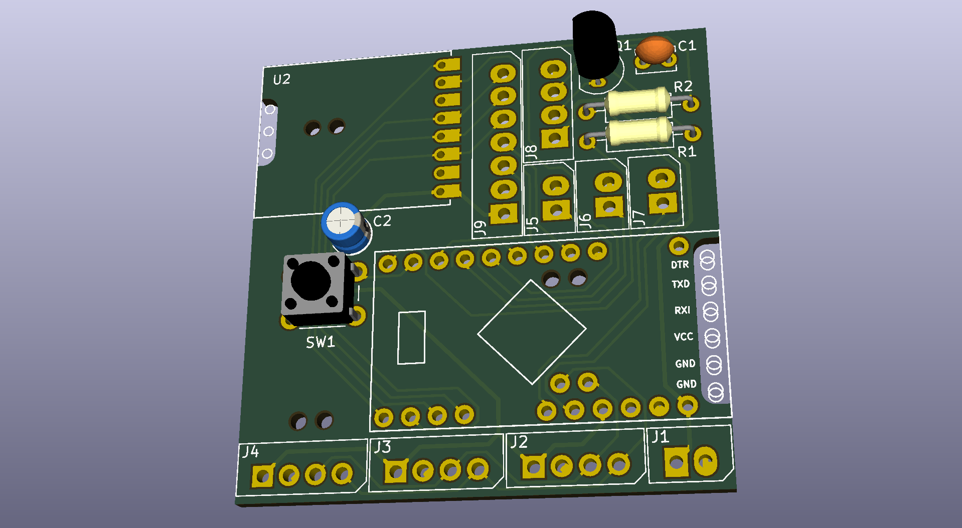
Benötigte Bauteile:

  • Arduino Pro Mini 3.3V 8Mhz (The Simple)
  • CC1101 Modulplatine 868MHz
  • Elko 10uF 1,5mm
  • Mikroschalter 6*6mm
  • Kerko 1nf RM 2.5mm
  • 10K Widerstand
  • 100K Widerstand
  • MPSA13 TO-92
  • 4x Molex Spox 2-pol (Alternativ Stiftleiste oder Kabel direkt anlöten)
  • 4x Molex Spox 4-pol (Alternativ Stiftleiste oder Kabel direkt anlöten)
  • 1x Molex Spox 7-pol (Alternativ Stiftleiste oder Kabel direkt anlöten)
  • Stiftleiste RM 2mm 1x8 Pin (Für CC1101)

Hinweise

  • Achtung: kein Verpolungs- oder Überspannungschutz vorhanden
  • Am I2C sind keine Pullups vorhanden, da diese im Regelfall auf I2C Platinen bereits integriert sind

Parts

96
QtyValueFootprintReferences
1510KResistor_SMD:R_0402_1005MetricR1, R2, R5, R7, R8, R19, R20, R21, R25, R26, R27, R29, R30, R32, R35
8100nCapacitor_SMD:C_0402_1005MetricC2, C7, C10, C14, C16, C19, C20, C26
622uCapacitor_SMD:C_0603_1608MetricC6, C9, C12, C13, C22, C24
41KResistor_SMD:R_0402_1005MetricR3, R17, R23, R24
42KResistor_SMD:R_0402_1005MetricR6, R31, R33, R34
449.9RResistor_SMD:R_0402_1005MetricR13, R14, R15, R16
4S8050Package_TO_SOT_SMD:SOT-23Q1, Q2, Q4, Q5
3100RResistor_SMD:R_0402_1005MetricR4, R9, R10
210nCapacitor_SMD:C_0402_1005MetricC15, C21
210uCapacitor_SMD:C_0603_1608MetricC3, C25
2470uCapacitor_THT:CP_Radial_D8.0mm_P3.50mmC1, C8
2AO3401APackage_TO_SOT_SMD:SOT-23Q3, Q6
2I2C_PULLUPJumper:SolderJumper-2_P1.3mm_Open_RoundedPad1.0x1.5mmJP1, JP2
2dnpCapacitor_SMD:C_0402_1005MetricC17, C18
11.5KE68CADiode_THT:D_DO-201AE_P5.08mm_Vertical_KathodeUpD4
1100KResistor_SMD:R_0402_1005MetricR28
1100uCapacitor_Tantalum_SMD:CP_EIA-3528-15_AVX-HC27
112.1KResistor_SMD:R_0402_1005MetricR12
11MResistor_SMD:R_0402_1005MetricR22
11uCapacitor_SMD:C_0603_1608MetricC5
122nCapacitor_SMD:C_0402_1005MetricC11
1330RResistor_SMD:R_0402_1005MetricR18
133RResistor_SMD:R_0402_1005MetricR11
1470pCapacitor_SMD:C_0402_1005MetricC4
1AMS1117-3.3Package_TO_SOT_SMD:SOT-223-3_TabPin2U1
1BTNButton_Switch_THT:SW_PUSH_6mmSW1
1CH340CPackage_SO:SOIC-16_3.9x9.9mm_P1.27mmU4
1CON_DCFConnector_PinHeader_2.54mm:PinHeader_1x03_P2.54mm_VerticalJ5
1CON_GPIOConnector_PinHeader_2.54mm:PinHeader_2x20_P2.54mm_VerticalJ1
1CON_I2CConnector_PinHeader_2.54mm:PinHeader_1x05_P2.54mm_VerticalJ4
1ESP32-WROOM-32Homebrew:ESP32-WROOM-32_HandsolderingU3
1FB/100RInductor_SMD:L_0805_2012MetricL2
1FB/600RInductor_SMD:L_0805_2012MetricL1
1HY931147CHomebrew:RJ45_Hanrun_HY934711CJ2
1LAN8720APackage_DFN_QFN:QFN-24-1EP_4x4mm_P0.5mm_EP2.6x2.6mm_ThermalViasU2
1LED_PowerLED_SMD:LED_0603_1608Metric_CastellatedD2
1LED_StatusLED_SMD:LED_0603_1608Metric_CastellatedD1
1RT9400Homebrew:RT9400U5
1SRV05-4Package_TO_SOT_SMD:SOT-23-6U6
1SS34Diode_SMD:D_SMAD3
1USB_B_MicroHomebrew:U-F-M5DD-Y-1J3
1dnpCrystal:Crystal_SMD_3225-4Pin_3.2x2.5mmY1

The 88 most common of 96 parts.

More from alexreinert/PCB

2
  • 2 layers85 × 56 mmHB RF USB-2, the printed circuit board in 3D

    HB RF USB-2

    alexreinert/PCB

    Some of my PCBs

    35 parts104
  • 2 layers47.6 × 52.1 mmHB RF USB, the printed circuit board in 3D

    HB RF USB

    alexreinert/PCB

    Some of my PCBs

    27 parts104

Similar boards

  • 4 layers100 × 100 mmNif T, the printed circuit board in 3D

    Nif T

    SharKingStudios/Nif-T

    An all in one smart home automation board!

    115 parts11MIT
  • 2 layers49.4 × 95.7 mmPhysiowand, the printed circuit board in 3D

    Physiowand

    1tsMS/Physiowand

    91 parts
  • 2 layers65 × 65 mmRC CAR V2, the printed circuit board in 3D

    RC CAR V2

    yamahdee/KICAD-RC-CAR

    68 parts
  • 2 layers99 × 90 mmHomeyPCB, the printed circuit board in 3D

    HomeyPCB

    jadam3k/Homey

    Home Asistance/Industrial PLC

    99 parts
  • 2 layers35 × 45 mmLVGLDevKit, the printed circuit board in 3D

    LVGLDevKit

    jppang/ESP32_MicroPython_LVGL_ST7789

    Try to build an ESP32 firmware with LVGL and ST7789 drivers inside.

    40 parts2
  • 4 layers100 × 80 mmHackathon board v2, the printed circuit board in 3D

    Hackathon board v2

    Brian-Nziza/ESP32-Hackathon-Board

    KiCad 10 project. Board is 100 × 80 mm, four layers, fabricated by JLCPCB.

    75 parts

Questions

How big is the HB RF ETH PCB?

It measures 85 × 56 mm and has 2 copper layers, 1.6 mm thick.

What parts does the HB RF ETH use?

96 parts, built around the CH340C, ESP32-WROOM-32, AMS1117-3.3 and LAN8720A-CP. The full list of its parts is on this page, with links to each part's symbol and footprint where PCBKit's library has them.

Where can I download the HB RF ETH KiCad files?

From the alexreinert/PCB repository on GitHub, at the commit this page was made from: the board is HB-RF-ETH/HB-RF-ETH.kicad_pcb. PCBKit opens the board in the browser, with nothing to install.

Can I use the HB RF ETH design in my own project?

Its repository states no licence, so its author keeps all rights: ask alexreinert before reusing the design.