4 layers104 × 168 mm

 robotont/robotont-electronics-mainboard1
Unified pcb design for the 3rd generation robotont robot.
Robotont electronics mainboard is an open-source printed circuit board by robotont, from the robotont/robotont-electronics-mainboard repository on GitHub. It is a 2-layer board of 304.3 × 274 mm with 426 parts on 307 nets, routed with 2,904 tracks and 1,316 vias.
It is built around the ATTINY88-AU, SN74LV1T34DBV and TPS56339DDC, with the ADUM1201ARZ-RL7, INA138NA and TXS0102DCU among its other parts. Its parts include 163 capacitors, 97 resistors, 75 diodes, 18 ICs and 14 transistors. It belongs with the robots and motor control and computers and single-board computers boards and the AVR (ATmega, ATtiny) boards of this library.


This repository contains electronics schematics and PCB layout of the Robotont 3 mainboard. The project is developed in KiCAD 8 and offers production files for JLCPCB.
The scematics of this project have been organized into multiple hierarchical sheets according to the robot subsystems. An outline of the pdf is as follows:
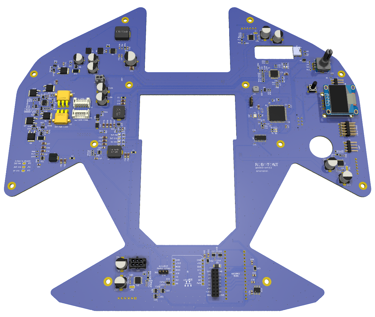
The following 3D rendering illustrates the PCB design of the Robotont 3 mainboard.
If you're on Ubuntu, here's a snippet:
    sudo add-apt-repository ppa:kicad/kicad-9.0-releases -y
    sudo apt update
sudo apt install --install-recommends kicadThis plugin helps to manage rotations and generate production files. See installation instructions in the plugin repository.
git clone https://github.com/robotont/robotont-electronics-mainboard.gitThe production files for JLCPCB are available in the jlcpcb/production_files/ directory.
GERBER-mainboard.zip) to JLCPCB PCB order wizard.BOM-mainboard.csv) and CPL (CPL-mainboard.csv) files to the assembly wizard.| Qty | Value | Footprint | References |
|---|---|---|---|
| 84 | 100nF | Capacitor_SMD:C_0402_1005Metric | C100, C101, C102, C103, C104, C105, C106, C107, C108, C109, C110, C111, C112, C113, C114, C115 +68 |
| 60 | WS2812B | Robotont:LED3535 | D10, D11, D12, D13, D14, D15, D16, D17, D18, D19, D20, D21, D22, D23, D24, D25 +44 |
| 20 | 100k | Resistor_SMD:R_0603_1608Metric | R7, R20, R22, R26, R27, R30, R34, R60, R61, R63, R64, R66, R79, R80, R85, R196 +4 |
| 20 | 10k | Resistor_SMD:R_0603_1608Metric | R1, R13, R17, R25, R29, R37, R41, R45, R49, R53, R55, R59, R67, R68, R197, R297 +4 |
| 13 | 100nF | Capacitor_SMD:C_0805_2012Metric | C37, C47, C53, C54, C60, C61, C62, C63, C64, C68, C69, C74, C75 |
| 12 | SpacerMountingHole_3.5mm | Robotont:SpacerMountingHole_3.5mm | H1, H2, H3, H4, H5, H6, H7, H8, H9, H10, H11, H12 |
| 11 | 1k | Resistor_SMD:R_0603_1608Metric | R24, R28, R33, R62, R65, R77, R78, R84, R94, R98, R296 |
| 10 | 10uF | Capacitor_SMD:C_1206_3216Metric | C1, C33, C34, C51, C52, C58, C59, C66, C67, C156 |
| 9 | 1pF | Capacitor_SMD:C_0402_1005Metric | C21, C22, C23, C28, C29, C30, C78, C79, C80 |
| 8 | 220uF | Capacitor_SMD:CP_Elec_8x10.5 | C27, C77, C84, C85, C86, C87, C154, C155 |
| 6 | 10nF | Capacitor_SMD:C_0402_1005Metric | C9, C18, C19, C20, C36, C159 |
| 6 | 22uF | Capacitor_SMD:C_1206_3216Metric | C48, C49, C55, C56, C70, C71 |
| 6 | AO3400A | Package_TO_SOT_SMD:SOT-23 | Q2, Q6, Q9, Q11, Q12, Q22 |
| 6 | LED_G | LED_SMD:LED_0603_1608Metric | D1, D64, D65, D66, D67, D72 |
| 6 | NCE60P25K | Package_TO_SOT_SMD:TO-252-2 | Q1, Q3, Q5, Q10, Q13, Q21 |
| 6 | SN74LV1T34DBV | Package_TO_SOT_SMD:SOT-23-5 | U16, U17, U18, U19, U20, U21 |
| 5 | 12 V | Diode_SMD:D_SOD-123 | D2, D76, D77, D103, D104 |
| 5 | 1uF | Capacitor_SMD:C_0603_1608Metric | C10, C11, C157, C158, C162 |
| 5 | 2.2uF | Capacitor_SMD:C_0805_2012Metric | C13, C14, C45, C160, C161 |
| 4 | 120 | Resistor_SMD:R_0603_1608Metric | R6, R10, R11, R12 |
| 4 | 4k7 | Resistor_SMD:R_0603_1608Metric | R69, R70, R82, R91 |
| 4 | 51k | Resistor_SMD:R_0603_1608Metric | R16, R47, R54, R58 |
| 3 | 10pF | Capacitor_SMD:C_0603_1608Metric | C16, C17, C165 |
| 3 | 16k | Resistor_SMD:R_0805_2012Metric | R14, R18, R56 |
| 3 | 1k2 | Resistor_SMD:R_0603_1608Metric | R42, R51, R90 |
| 3 | 1k5 | Resistor_SMD:R_0603_1608Metric | R15, R19, R57 |
| 3 | 30R | Resistor_SMD:R_0603_1608Metric | R44, R48, R50 |
| 3 | 33nF | Capacitor_SMD:C_0603_1608Metric | C24, C31, C81 |
| 3 | 39uF | Robotont:CAP-SMD_BD8.0-L8.3-W8.3-LS9.0-FD_35SVPF39M | C38, C39, C40 |
| 3 | 47uF | Capacitor_SMD:C_1206_3216Metric | C50, C57, C65 |
| 3 | BSMD1206-300-6V | Fuse:Fuse_1206_3216Metric_Pad1.42x1.75mm_HandSolder | F1, F2, F3 |
| 3 | DRV8874PWPR | Robotont:HTSSOP-16-1EP_4.4x5mm_P0.65mm_EP3.4x5mm_Mask3x3mm_ThermalVias | U4, U5, U6 |
| 3 | PinHeader_1x06 | Connector_PinHeader_2.54mm:PinHeader_1x06_P2.54mm_Horizontal | J5, J6, J7 |
| 3 | SolderJumper | Jumper:SolderJumper-3_P1.3mm_Bridged12_Pad1.0x1.5mm | JP6, JP7, JP8 |
| 3 | SolderJumper_2_Open | Jumper:SolderJumper-2_P1.3mm_Open_RoundedPad1.0x1.5mm | JP2, JP3, JP5 |
| 3 | TPS56339DDC | Package_TO_SOT_SMD:TSOT-23-6 | U10, U11, U15 |
| 2 | 120R | Resistor_SMD:R_0805_2012Metric | FB1, FB2 |
| 2 | 18k | Resistor_SMD:R_0603_1608Metric | R21, R23 |
| 2 | 220R | Resistor_SMD:R_0603_1608Metric | R35, R36 |
| 2 | 30k | Resistor_SMD:R_0603_1608Metric | R43, R52 |
| 2 | 4.7uH | Robotont:IND-FXL1040-4R7-M | L2, L4 |
| 2 | 470R | Resistor_SMD:R_0603_1608Metric | R83, R89 |
| 2 | 47R | Resistor_SMD:R_0603_1608Metric | R2, R5 |
| 2 | 5k1 | Resistor_SMD:R_0603_1608Metric | R3, R4 |
| 2 | Conn_01x04_Pin | Connector_PinHeader_2.54mm:PinHeader_1x04_P2.54mm_Horizontal | J3, J17 |
| 2 | D_Schottky | Diode_SMD:D_SMA | D68, D69 |
| 2 | INA138 | Package_TO_SOT_SMD:SOT-23-5 | U8, U22 |
| 2 | LED_R | LED_SMD:LED_0603_1608Metric | D71, D73 |
| 2 | TXS0102DCU | Package_SO:VSSOP-8_2.3x2mm_P0.5mm | U12, U13 |
| 2 | ~ | Connector_PinHeader_2.54mm:PinHeader_1x03_P2.54mm_Vertical | JP1, JP4 |
| 1 | 0R | Resistor_SMD:R_0603_1608Metric | R32 |
| 1 | 100uF | Capacitor_SMD:C_1210_3225Metric | C44 |
| 1 | 10m | Resistor_SMD:R_2512_6332Metric | R73 |
| 1 | 120uF | Robotont:CAP-SMD_BD10.0-L10.3-W10.3-FD_EEHZC1E331P | C43 |
| 1 | 150k | Resistor_SMD:R_0603_1608Metric | R31 |
| 1 | 15nF | Capacitor_SMD:C_0603_1608Metric | C46 |
| 1 | 16Mhz | Crystal:Crystal_SMD_3225-4Pin_3.2x2.5mm | Y1 |
| 1 | 191k | Resistor_SMD:R_0805_2012Metric_Pad1.20x1.40mm_HandSolder | R39 |
| 1 | 1k43 | Resistor_SMD:R_0805_2012Metric_Pad1.20x1.40mm_HandSolder | R40 |
| 1 | 200k | Resistor_SMD:R_0603_1608Metric | R72 |
| 1 | 2k4 | Resistor_SMD:R_0603_1608Metric | R46 |
| 1 | 300k | Resistor_SMD:R_0603_1608Metric | R74 |
| 1 | 4.7uH | Robotont:IND-FXL1360_12.6x13.5mm | L1 |
| 1 | 470nF | Capacitor_SMD:C_0805_2012Metric | C41 |
| 1 | 470pF | Capacitor_SMD:C_0805_2012Metric | C42 |
| 1 | 5.6uH | Inductor_SMD:L_Changjiang_FXL0630 | L3 |
| 1 | 510k | Resistor_SMD:R_0603_1608Metric | R38 |
| 1 | 5m | Resistor_SMD:R_2512_6332Metric | R71 |
| 1 | ADUM1201ARZ-RL7 | Package_SO:SOIC-8_3.9x4.9mm_P1.27mm | U14 |
| 1 | ATtiny88-A | Package_QFP:TQFP-32_7x7mm_P0.8mm | U7 |
| 1 | AVR-ISP-6 | Connector_PinHeader_2.54mm:PinHeader_2x03_P2.54mm_Horizontal | J12 |
| 1 | Arduino_Nano | Robotont:Arduino_Nano | A1 |
| 1 | CSD17577Q5A | Package_TO_SOT_SMD:TDSON-8-1 | Q7 |
| 1 | CSD18540Q5B | Package_TO_SOT_SMD:TDSON-8-1 | Q8 |
| 1 | Conn_01x02_Pin | Robotont:Molex_Micro-Fit_3.0_43045-0212_2x01_P3.00mm_Vertical | J16 |
| 1 | Conn_01x04_Socket | Robotont:SSD1306_0.96_Oled | J2 |
| 1 | Conn_01x06_Pin | Connector_JST:JST_PH_S6B-PH-K_1x06_P2.00mm_Horizontal | J8 |
| 1 | Conn_01x06_Pin_BAT_data | Connector_JST:JST_PH_S6B-PH-K_1x06_P2.00mm_Horizontal | J9 |
| 1 | Conn_02x08_Odd_Even | Connector_PinSocket_2.54mm:PinSocket_2x08_P2.54mm_Vertical | J19 |
| 1 | ESTOP CONN | Robotont:Molex_Micro-Fit_3.0_43045-0612_2x03_P3.00mm_Vertical | J13 |
The 410 most common of 426 parts.
It measures 304.3 × 274 mm and has 2 copper layers, 1.6 mm thick.
426 parts, built around the ATTINY88-AU, SN74LV1T34DBV, TPS56339DDC and ADUM1201ARZ-RL7. The full list of its parts is on this page, with links to each part's symbol and footprint where PCBKit's library has them.
From the robotont/robotont-electronics-mainboard repository on GitHub, at the commit this page was made from: the board is mainboard.kicad_pcb and its schematic dc_dc_12v_motors.kicad_sch. PCBKit opens the board in the browser, with nothing to install.
Its repository states no licence, so its author keeps all rights: ask robotont before reusing the design.


FumBlau/universal_lights
PCB and firmware for RGB and single color control based on attiny88

IowaScaledEngineering/mss-xcade
Modular Signal System 4 Port Complex Cascade


HeyPCB/quack-core
Brain board for the Open Duck Mini: Pi Zero 2W carrier, 14-servo STS bus, fused 2S power path in stitched copper zones (15-18 A battery side), USB-C charging with balancing, IMU.