2 layers188.1 × 58.2 mm
AN ESP32 S3
laforestlabs/KiCraft
KiCad PCB automation toolkit — placement, routing, scoring, and experiment management
36 parts

 rhammell/mdd32-bot
A compact ESP32-S3 based differential drive controller board designed in KiCad
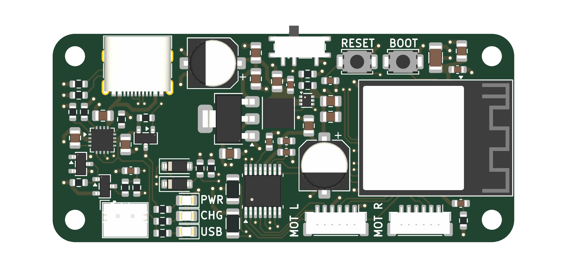
Mdd32-bot is an open-source printed circuit board by rhammell, from the rhammell/mdd32-bot repository on GitHub, published under the MIT licence. It is a 4-layer board of 62 × 28 mm with 66 parts on 83 nets, routed with 511 tracks and 99 vias.
It is built around the ESP32-S3-MINI-1-N8, DRV8833PWPR and BQ24072RGTR, with the AO3401A and SD103AW among its other parts. Its parts include 22 capacitors, 19 resistors, 5 ICs, 5 diodes and 4 connectors. It belongs with the robots and motor control boards and the ESP32 boards of this library.


A minimal two-wheeled differential-drive robot built around an ESP32-S3. The project includes the custom PCB, the 3D-printable chassis, and the firmware (packaged as an Arduino library).
The MDD32 board is a small, battery-powered controller for two-wheeled robots. It pairs an ESP32-S3 module with a dual H-bridge motor driver and connectors for two N20 gear motors with quadrature encoders. A single-cell Li-ion/LiPo battery powers the board, and it charges over USB-C. The same USB-C port is used for programming and serial debugging through the ESP32-S3's native USB.
| Folder | Description |
|---|---|
firmware/ | ESP32 firmware, packaged as the MDD32_Bot Arduino library, plus example, test, and tuning sketches. |
hardware/ | KiCad project for the PCB (schematic, board layout, and footprint/symbol/3D-model libraries). |
mechanical/ | FreeCAD source (mechanical/src/) and exported STLs (mechanical/export/) for the chassis. |
images/ | README images. |
| Rail | Source | Feeds |
|---|---|---|
VBUS | USB-C (5 V) | Battery charger input |
VBAT | 1S Li-ion/LiPo via JST-PH 2-pin | Charger battery pin |
VSYS | Charger power-path output, through the power switch | LDO and boost converter |
+3V3 | AP2114H-3.3 LDO | ESP32-S3 and encoders |
+5V | TPS61023 boost (≈4.96 V) | DRV8833 motor supply |
| GPIO | Signal | Function |
|---|---|---|
| IO0 | BOOT | BOOT button (strapping pin) |
| EN | RESET | RESET button |
| IO10 | VBAT_MON | Battery voltage, ½ divider (ADC) |
| IO35 | PGOOD_MON | USB power present (active low) |
| IO36 | CHG_MON | Charging (active low) |
| IO40 | SLEEP | DRV8833 nSLEEP (high = enabled) |
| IO47 | MOT1_IN1 | Left motor driver input 1 (AIN1) |
| IO33 | MOT1_IN2 | Left motor driver input 2 (AIN2) |
| IO38 | MOT1_ENCA | Left encoder channel A |
| IO39 | MOT1_ENCB | Left encoder channel B |
| IO48 | MOT2_IN1 | Right motor driver input 1 (BIN1) |
| IO34 | MOT2_IN2 | Right motor driver input 2 (BIN2) |
| IO41 | MOT2_ENCA | Right encoder channel A |
| IO42 | MOT2_ENCB | Right encoder channel B |
| IO19/20 | USB_D-/USB_D+ | Native USB |
| Ref | Connector | Pinout |
|---|---|---|
| J1 | JST-PH 2-pin | 1: VBAT, 2: GND |
| J2 | USB-C (USB 2.0) | Power and data |
| J4 | JST-SH 6-pin (MOT L) | 1: GND, 2: ENC_B, 3: ENC_A, 4: 3V3, 5: M2, 6: M1 |
| J5 | JST-SH 6-pin (MOT R) | 1: GND, 2: ENC_B, 3: ENC_A, 4: 3V3, 5: M2, 6: M1 |
hardware/MDD32_Bot/MDD32_Bot.kicad_pro in KiCad 10 or newer.LCSC field for JLCPCB assembly. The Fabrication Toolkit plugin can generate the Gerbers, BOM, and placement file in one step.The firmware lives in firmware/MDD32_Bot/, structured as an Arduino library with no external dependencies:
| Path | Description |
|---|---|
src/MDD32_Bot.h / .cpp | Top-level MDD32_Bot class that ties the subsystems together. |
src/definitions/ | Compile-time configuration: pin_definitions.h (wiring) and robot_definitions.h (tuning/behavior). |
src/battery/ | MDD32_Battery: battery voltage and charger-status monitoring. |
src/drive/ | Differential drive stack: MDD32_Motor, MDD32_Encoder, MDD32_PID, MDD32_Motor_Controller, and MDD32_Drive. |
examples/Basics/ | Standalone feature demos: BatteryTest, WifiTest. |
examples/Tuning/ | Calibration sketches, numbered in the order they should be run: 1_PIDTuning, 2_WheelSyncTuning, 3_DistanceTuning. |
| All sketches report over the Serial Monitor at 115200 baud. |
Copy or symlink firmware/MDD32_Bot into your Arduino libraries folder (for example ~/Documents/Arduino/libraries/MDD32_Bot), and install the esp32 by Espressif Systems board package.
In the Arduino IDE, select ESP32S3 Dev Module and set:
The ESP32-S3 is programmed over USB-C. If the port doesn't appear, hold BOOT, press and release RESET, then release BOOT to enter the bootloader.
Include the library and create a single MDD32_Bot instance. It exposes two subsystems as public members: battery and drive.
#include <MDD32_Bot.h>

MDD32_Bot bot;

void setup() {
    Serial.begin(115200);
    if (!bot.begin()) {
        Serial.println("MDD32 Bot init failed");
        while (1);
    }
    bot.drive.straight(6.0f);   // drive forward at 6 cm/s
}

void loop() {
    bot.drive.update();         // must be called frequently for PID control
}MDD32_Bot| Member | Description |
|---|---|
bool begin() | Initializes the battery monitor and drive subsystems. Returns false if either fails. |
battery | MDD32_Battery instance (see below). |
drive | MDD32_Drive instance (see below). |
MDD32_Battery| Method | Description |
|---|---|
bool begin() | Initializes battery voltage and charge-status monitoring. Called by MDD32_Bot::begin(). |
float voltage() | Battery voltage in volts. |
bool charging() | true while actively charging. |
bool chargerConnected() | true when a charging source is plugged in. |
MDD32_DriveDifferential drive with per-wheel PID speed control, acceleration ramping, and wheel-sync correction. Call update() frequently from loop() to run the control loop.
| Method | Description |
|---|---|
bool begin() | Initializes the motor driver, both motor controllers, and encoders. Called by MDD32_Bot::begin(). |
void straight(float speed_cm_s) | Drives both wheels at the given speed (negative = reverse). Clamped to MAX_SPEED_CM_S. |
void spin(float speed_cm_s) | Spins in place, with the wheels at equal and opposite speeds. Positive spins clockwise. |
void stop() | Stops both motors immediately and goes idle. |
void update() | Runs the drive control loop; call as often as possible. |
bool isMoving() | true while a drive command is active. |
DriveTelemetry getTelemetry() | Returns current motor telemetry. |
float getDistance() | Returns cumulative straight-line distance, in cm, driven since power-on. Spins don't add to it. |
void resetDistance() | Resets the cumulative drive distance to zero. |
DriveTelemetry contains: leftRPM, leftPWM, rightRPM, rightPWM, leftCount, and rightCount (wheel-output RPM, applied PWM, and raw encoder counts).
The control parameters default to the values in src/definitions/robot_definitions.h. These setters override them at runtime; call them after bot.begin(). The sketches in examples/Tuning/ use them so you can tune without editing the library.
| Method | Description |
|---|---|
void setPIDGains(float kp, float ki, float kd) | Sets the PID gains for both wheels. Default: PID_KP, PID_KI, PID_KD. |
void setWheelSyncKP(float kp) | Sets the wheel-sync correction gain (0 disables it). Default: WHEEL_SYNC_KP. |
void setMaxAccel(float rpmPerSec) | Sets the acceleration ramp rate (0 disables ramping). Default: MAX_ACCEL_RPM_S. |
This project, including the firmware, PCB design files, and mechanical/3D-printed parts, is licensed under the MIT License.
| Qty | Value | Footprint | References |
|---|---|---|---|
| 6 | 10uF | Capacitor_SMD:C_0805_2012Metric | C6, C9, C10, C15, C16, C20 |
| 5 | 0.1uF | Capacitor_SMD:C_0603_1608Metric | C2, C3, C7, C14, C19 |
| 5 | 22uF | Capacitor_SMD:C_0805_2012Metric | C4, C12, C18, C21, C22 |
| 4 | 100k | Resistor_SMD:R_0603_1608Metric | R2, R3, R4, R11 |
| 4 | 10k | Resistor_SMD:R_0603_1608Metric | R1, R7, R8, R12 |
| 4 | MountingHole | MountingHole:MountingHole_2.7mm_M2.5 | H1, H2, H3, H4 |
| 3 | 4.7k | Resistor_SMD:R_0603_1608Metric | R15, R18, R19 |
| 3 | LED | LED_SMD:LED_0805_2012Metric | D3, D4, D5 |
| 2 | 300m | Resistor_SMD:R_1206_3216Metric | R13, R14 |
| 2 | 470uF | Capacitor_SMD:CP_Elec_6.3x7.7 | C8, C17 |
| 2 | 5.1k | Resistor_SMD:R_0603_1608Metric | R5, R6 |
| 2 | AO3401A | Package_TO_SOT_SMD:SOT-23 | Q1, Q3 |
| 2 | Conn_Motor_N20_Encoder | Connector_JST:JST_SH_BM06B-SRSS-TB_1x06-1MP_P1.00mm_Vertical | J4, J5 |
| 2 | SD103AW | Diode_SMD:D_SOD-123 | D1, D2 |
| 1 | 0.01uF | Capacitor_SMD:C_0603_1608Metric | C13 |
| 1 | 1.1k | Resistor_SMD:R_0603_1608Metric | R9 |
| 1 | 100uF | Capacitor_SMD:C_1206_3216Metric | C5 |
| 1 | 1uF | Capacitor_SMD:C_0603_1608Metric | C1 |
| 1 | 1uH | MDD32_Bot:L_Coilcraft_XxL4030 | L1 |
| 1 | 2.2uF | Capacitor_SMD:C_0603_1608Metric | C11 |
| 1 | 2.7k | Resistor_SMD:R_0603_1608Metric | R10 |
| 1 | 220k | Resistor_SMD:R_0603_1608Metric | R16 |
| 1 | 2N7002 | Package_TO_SOT_SMD:SOT-23 | Q2 |
| 1 | 30k | Resistor_SMD:R_0603_1608Metric | R17 |
| 1 | AP2114H-3.3 | Package_TO_SOT_SMD:SOT-223-3_TabPin2 | U4 |
| 1 | BQ24072RGT | MDD32_Bot:VQFN-16-1EP_3x3mm_P0.5mm_EP1.6x1.6mm_ThermalVias | U2 |
| 1 | DRV8833PWPR | MDD32_Bot:HTSSOP-16-1EP_4.4x5mm_P0.65mm_EP3.4x5mm_Mask2.66x2.46mm_ThermalVias | U3 |
| 1 | ESP32-S3-MINI-1 | MDD32_Bot:ESP32-S3-MINI-1 | U1 |
| 1 | JST_PH | Connector_JST:JST_PH_B2B-PH-K_1x02_P2.00mm_Vertical | J1 |
| 1 | SW_BOOT | Button_Switch_SMD:SW_SPST_TS-1088-xR020 | SW2 |
| 1 | SW_RESET | Button_Switch_SMD:SW_SPST_TS-1088-xR020 | SW1 |
| 1 | SW_SPDT_SH | MDD32_Bot:SW_SPDT_Shouhan_MSK12C02 | SW3 |
| 1 | TPS61023DRLR | Package_TO_SOT_SMD:SOT-563 | U5 |
| 1 | USB_C_Receptacle_USB2.0_16P | MDD32_Bot:USB_C_Receptacle_G-Switch_GT-USB-7010ASV | J2 |
It measures 62 × 28 mm and has 4 copper layers, 1.6 mm thick.
66 parts, built around the ESP32-S3-MINI-1-N8, DRV8833PWPR, BQ24072RGTR and AO3401A. The full list of its parts is on this page, with links to each part's symbol and footprint where PCBKit's library has them.
From the rhammell/mdd32-bot repository on GitHub, at the commit this page was made from: the board is hardware/MDD32_Bot/MDD32_Bot.kicad_pcb and its schematic hardware/MDD32_Bot/MDD32_Bot.kicad_sch. PCBKit opens the board in the browser, with nothing to install.
Its repository publishes it under the MIT licence: you may reuse it on that licence's terms (keep the author's notice, and for a copyleft licence share your changes alike).
laforestlabs/KiCraft
KiCad PCB automation toolkit — placement, routing, scoring, and experiment management

DesignStraub/ringwheel-hybrid-drone
A 5-inch FPV drone whose prop ducts fold down and become wheels. Design study in Fusion 360 and KiCad, CC BY-NC-SA 4.0.


little-red-rover/lrr-hardware
Hardware design files for Little Red Rover.

Jan-Philipp-Munsch/kartonaut
TVC model rocket (after BPS.space Scout F): Teensy 4.1 flight firmware, mainboard spec, project log

LlamaLuLu/Micromouse-Lula-and-Rejoice
Our Micromouse power subsystem for the Design course EEE3088F

ryandrake08/billy
Offline Big Mouth Billy Bass voice jokester powered by an ESP32-S3 and a local GPU backend.

SFBdragon/eee3088f-project
Collaborative repo for the UCT EEE3088F Project of team 69.