2 layers57.6 × 40 mm
Texas InstrumentsExtended
-40℃~+85℃ 1.5A 2 2.7V~10.8V 360mΩ Bipolar Driver Yes TSSOP-16-EP Stepper Motor Driver ROHS
The DRV8833PWPR is a stepper Motor Driver made by Texas Instruments in a TSSOP-16-EP package with 17 pins. -40℃~+85℃ 1.5A 2 2.7V~10.8V 360mΩ Bipolar Driver Yes TSSOP-16-EP Stepper Motor Driver ROHS.
PCBKit's library has its KiCad symbol (Driver_Motor:DRV8833PWP, from KiCad's library) and its footprint (Package_SO:HTSSOP-16-1EP_4.4x5mm_P0.65mm_EP3.4x5mm_Mask2.46x2.31mm, from KiCad's library), ready for a KiCad board. 28,665 are in stock at JLCPCB (part C50506). 27 open-source boards in 21 repositories on GitHub use it.
| Parameter | Conditions | As printed | Page |
|---|---|---|---|
| Power supply voltage VM | over operating free-air temperature range | min -0.3 · max 11.8 V | 5 |
| Digital input pin voltage | over operating free-air temperature range | min -0.5 · max 7 V | 5 |
| xISEN pin voltage | over operating free-air temperature range | min -0.3 · max 0.5 V | 5 |
| Operating junction temperature TJ | min -40 · max 150 °C | 5 | |
| Storage temperature Tstg | min -60 · max 150 °C | 5 | |
| Electrostatic discharge V(ESD) | Human body model (HBM), per ANSI/ESDA/JEDEC JS-001, all pins | min -4000 · max 4000 V | 5 |
| Electrostatic discharge V(ESD) | Charged device model (CDM), per JEDEC specification JESD22-C101, all pins | min -1500 · max 1500 V | 5 |
| Motor power supply voltage range VM | TA = 25°C; RDS(ON) increases and maximum output current is reduced below 5 V | min 2.7 · max 10.8 V | 5 |
| Digital input pin voltage range VDIGIN | TA = 25°C | min -0.3 · max 5.75 V | 5 |
| Junction-to-ambient thermal resistance RθJA | PWP (HTSSOP), 16 pins | typ 40.5 °C/W | 5 |
| Junction-to-case (top) thermal resistance RθJC(top) | PWP (HTSSOP), 16 pins | typ 32.9 °C/W | 5 |
| Junction-to-board thermal resistance RθJB | PWP (HTSSOP), 16 pins | typ 28.8 °C/W | 5 |
| Junction-to-top characterization parameter ψJT | PWP (HTSSOP), 16 pins | typ 0.6 °C/W | 5 |
| Junction-to-board characterization parameter ψJB | PWP (HTSSOP), 16 pins | typ 11.5 °C/W | 5 |
| Junction-to-case (bottom) thermal resistance RθJC(bot) | PWP (HTSSOP), 16 pins | typ 4.8 °C/W | 5 |
| VM operating supply current IVM | TA = 25°C; VM = 5 V, xIN1 = 0 V, xIN2 = 0 V | typ 1.7 · max 3 mA | 6 |
| VM sleep mode supply current IVMQ | TA = 25°C; VM = 5 V | typ 1.6 · max 2.5 uA | 6 |
| VM undervoltage lockout voltage VUVLO | TA = 25°C; VM falling | max 2.6 V | 6 |
| VM undervoltage lockout hysteresis VHYS | TA = 25°C | typ 90 mV | 6 |
| Input low voltage VIL | TA = 25°C; nSLEEP | max 0.5 V | 6 |
| Input low voltage VIL | TA = 25°C; All other pins | max 0.7 V | 6 |
| Input high voltage VIH | TA = 25°C; nSLEEP | min 2.5 V | 6 |
| Input high voltage VIH | TA = 25°C; All other pins | min 2 V | 6 |
| Input hysteresis VHYS | TA = 25°C | typ 0.4 V | 6 |
| Input pulldown resistance RPD | TA = 25°C; nSLEEP | typ 500 kΩ | 6 |
| Input pulldown resistance RPD | TA = 25°C; All except nSLEEP | typ 150 kΩ | 6 |
| Input low current IIL | TA = 25°C; VIN = 0 | max 1 uA | 6 |
| Input high current IIH | TA = 25°C; VIN = 3.3 V, nSLEEP | typ 6.6 · max 13 uA | 6 |
| Input high current IIH | TA = 25°C; VIN = 3.3 V, all except nSLEEP | typ 16.5 · max 33 uA | 6 |
| Input deglitch time tDEG | TA = 25°C | typ 450 ns | 6 |
| Output low voltage VOL | TA = 25°C; nFAULT; IO = 5 mA | max 0.5 V | 6 |
| Output high leakage current IOH | TA = 25°C; nFAULT; VO = 3.3 V | max 1 uA | 6 |
| HS FET on resistance RDS(ON) | VM = 5 V, I O = 500 mA, TJ = 25°C | typ 200 mΩ | 6 |
| HS FET on resistance RDS(ON) | VM = 5 V, IO = 500 mA, TJ = 85°C | max 325 mΩ | 6 |
| HS FET on resistance RDS(ON) | VM = 2.7 V, I O = 500 mA, TJ = 25°C | typ 250 mΩ | 6 |
| HS FET on resistance RDS(ON) | VM = 2.7 V, IO = 500 mA, TJ = 85°C | max 350 mΩ | 6 |
| LS FET on resistance RDS(ON) | VM = 5 V, I O = 500 mA, TJ = 25°C | typ 160 mΩ | 6 |
| LS FET on resistance RDS(ON) | VM = 5 V, IO = 500 mA, TJ = 85°C | max 275 mΩ | 6 |
| LS FET on resistance RDS(ON) | VM = 2.7 V, I O = 500 mA, TJ = 25°C | typ 200 mΩ | 6 |
| LS FET on resistance RDS(ON) | VM = 2.7 V, IO = 500 mA, TJ = 85°C | max 300 mΩ | 6 |
| Off-state leakage current IOFF | VM = 5 V, TJ = 25°C, VOUT = 0 V | min -1 · max 1 uA | 6 |
| Current control PWM frequency ƒPWM | TA = 25°C; Internal PWM frequency | typ 50 kHz | 6 |
| Rise time tR | TA = 25°C; VM = 5 V, 16 Ω to GND, 10% to 90% VM | typ 180 ns | 6 |
| Fall time tF | TA = 25°C; VM = 5 V, 16 Ω to GND, 10% to 90% VM | typ 160 ns | 6 |
| Propagation delay INx to OUTx tPROP | TA = 25°C; VM = 5 V | typ 1.1 us | 6 |
| Dead time tDEAD | TA = 25°C; VM = 5 V; internal dead time | typ 450 ns | 6 |
| Overcurrent protection trip level IOCP | TA = 25°C | min 2 · typ 3.3 A | 6 |
| OCP Deglitch time tDEG | TA = 25°C | min 4 us | 6 |
| Overcurrent protection period tOCP | TA = 25°C | typ 1.35 ms | 6 |
| Thermal shutdown temperature tTSD | Die temperature | min 150 · typ 160 · max 180 °C | 6 |
| xISEN trip voltage VTRIP | TA = 25°C | min 160 · typ 200 · max 240 mV | 7 |
| Current sense blanking time tBLANK | TA = 25°C | typ 3.75 us | 7 |
| Start-up time tWAKE | TA = 25°C; nSLEEP inactive high to H-bridge on | max 1 ms | 7 |
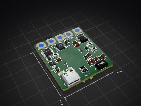

kocer/direct-sampling-sdr
Direct-sampling SDR transceiver with four phase-coherent channels, and a class-A power amplifier for 1.8 to 54 MHz.

wubneh/MCTR260-pico-firmware
Raspberry Pi Pico W robot controller firmware for MCTR 260 Mechatronics Design. Dual-core BLE architecture with mecanum drive, stepper/DC motor support, and configurable motion profiles.

ALECIA13/EEE3088F-2025
This repository contains the Power Module for a Micro-Mouse robot project, developed as part of the EEE3088F (2025) course.

BrandonC27-Engineer/Bloopy-Robot
Bloopy is a personal AI companion robot prototype integrating custom PCB designs, ESP32 sensors, Raspberry Pi processing, interactive OLED animations, and an AI-powered companion app.

DesignStraub/ringwheel-hybrid-drone
A 5-inch FPV drone whose prop ducts fold down and become wheels. Design study in Fusion 360 and KiCad, CC BY-NC-SA 4.0.

GoldenExperienceR/EEE3088F-Project-PCB-Files-Group-36-TRKJON002-MTMTAD006
EEE3088F Project Power PCB KiCad Design
Yes. The symbol is Driver_Motor:DRV8833PWP and the footprint Package_SO:HTSSOP-16-1EP_4.4x5mm_P0.65mm_EP3.4x5mm_Mask2.46x2.31mm, both drawn on this page. PCBKit places them on a board for you when you design with it.
TSSOP-16-EP, with 17 pins. Its footprint is drawn on this page.
Texas Instruments publishes it: the Datasheet link on this page opens it.
JLCPCB lists it as part C50506, with 28,665 in stock; the sellers' links on this page open their listings.
Parts like it in the library: the DRV8833PWP by Texas Instruments. Check their datasheets: a part that fits the footprint may still differ in its ratings.
27 boards in 21 repositories on GitHub; the most starred are listed on this page, with their KiCad files.
