2 layers76.5 × 71 mm
MM Power Subsystem
ALECIA13/EEE3088F-2025
This repository contains the Power Module for a Micro-Mouse robot project, developed as part of the EEE3088F (2025) course.
80 parts

 ALECIA13/EEE3088F-2025
This repository contains the Power Module for a Micro-Mouse robot project, developed as part of the EEE3088F (2025) course.
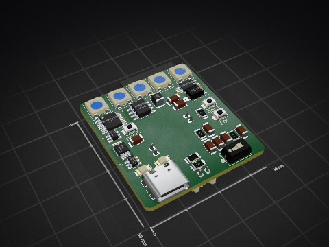
MM Power Subsystem is an open-source printed circuit board by ALECIA13, from the ALECIA13/EEE3088F-2025 repository on GitHub. It is a 2-layer board of 80 × 79 mm with 110 parts on 106 nets, routed with 859 tracks and 107 vias.
It is built around the DRV8833PWPR, LMR33630ADDA and CH224K, with the TPS613222ADBV, TPS22929DDBV and BQ24040DSQR among its other parts. Its parts include 28 resistors, 27 capacitors, 11 ICs, 3 diodes and 3 connectors. It belongs with the robots and motor control boards of this library.


Authors: Khanyisa Hlungwani & Maitele Makungo
This repository contains the Power Module for a Micro-Mouse robot project, developed as part of the EEE3088F (2025) course. The Micromouse is a small autonomous robot designed to navigate and solve a maze, consisting of various subsystems (sensors, motors, control, and power). The Power Module handles all aspects of power distribution and management for the robot, ensuring that each component receives stable and sufficient power. It includes the circuitry for the robot’s battery power supply, voltage regulation for logic and sensors, and motor driver outputs, along with safety features like battery monitoring and charging control. Overall, this module is crucial for delivering reliable power to the Micro-Mouse, allowing it to operate safely and efficiently during maze-solving runs.
The design and implementation of the Power Module were divided between two team members, each focusing on specific functional areas:
Khanyisa Hlungwani: Responsible for the motor control circuitry and battery management. This includes the motor driver hardware for the drive motors, the battery monitoring system to track battery voltage/health, and the battery charging circuit to safely recharge the robot’s Li-ion/Li-Po battery pack. Khanyisa’s design ensures the motors receive the appropriate power and that the battery is used and charged safely (with over-voltage and over-discharge protection as needed).
Maitele Makungo: Responsible for the power input interface and voltage regulation. This includes the USB-C interface for external power/charging (allowing the robot to be powered or charged via a USB-C source), the design of voltage regulators (to step down or regulate battery/USB voltage to the required levels for various components such as 5V, 3.3V, etc.), and overall power management circuitry. Maitele’s design ensures stable regulated voltages for all electronics and handles power switching logic (for example, switching between USB power and battery, and implementing any necessary protection like current limiting or short-circuit protection).
By splitting the responsibilities, each student focused on their section of the power system while ensuring that the two parts integrate seamlessly into a single Power Module that meets the Micro-Mouse’s requirements.
The repository is organized into folders and files that represent different aspects of the Power Module design:
Schematics – Contains the electrical schematics of the power module. This includes complete circuit diagrams for the battery charger/monitor, motor driver circuits, USB-C power input circuitry, and voltage regulators. The schematics are provided in the chosen EDA tool format (and may include PDF exports for easy viewing). (e.g., files like PowerModule_Schematic.pdf and the source schematic design files )
PCB Layout – Contains the PCB design files and layout information for the power module’s printed circuit board. This includes the board layout file from the PCB design software, as well as generated manufacturing files (Gerber files, drill files) and possibly images of the PCB layout. (e.g., a board file PowerModule_PCB.kicad_pcb or Altium project, and exported images like PCB_Top.png, PCB_Bottom.png )
Final Design – This folder includes the finalized documentation and outputs of the project. It typically contains the final report or design document for the power module, a Bill of Materials (BOM) listing all components used, and any presentation slides or additional references. It may also include final revision schematic/PCB printouts and assembly drawings, as well as test results or data from the completed module. In short, the Final Design folder serves as a comprehensive package of the finished power module design and can be used for review or submission purposes.
The Power Module is designed to integrate with the Micro-Mouse robot’s overall system (often via a main control board or motherboard). Key connections and usage notes include:
Power Input: The module can be powered via the on-board battery or through the USB-C port. When the Micro-Mouse is operating untethered, it draws power from the battery. When plugged into USB-C, the system can charge the battery and/or run the robot from USB power (with proper regulation and without overcharging the battery).
Outputs to Other Modules: The Power Module provides regulated output lines (e.g., 5V, 3.3V) that connect to the Micro-Mouse’s other subsystems (like the sensor module and control electronics) via a designated connector. It also provides the motor driver outputs that connect directly to the motors on the chassis. These interface connections are clearly labeled in the schematic and on the PCB silkscreen for easy assembly.
Battery Monitoring: The on-board battery voltage sensor can be read by the main controller (or a dedicated microcontroller on the power board) to determine the battery charge level. This allows the robot’s software to warn about low battery or manage charging states. Users should ensure the battery is within safe voltage ranges during operation (the module includes under-voltage lockout to protect the battery).
Charging: To charge the robot, connect a USB-C cable to the Power Module’s port. The charging circuit will automatically manage the charging current and cutoff based on the battery’s state. Indicator LEDs (if included on the PCB) may show the charging status (charging, full, etc.). It’s recommended to refer to the Final Design document for specifics on the charging procedure and any jumpers or switches related to power sourcing.
To get started with this Power Module repository:
Clone the Repository: Download or clone the repo to access all design files. Ensure you have the necessary software to open the schematic (Schematics folder) and PCB layout files (PCB Layout folder). For example, if the design was done in KiCad, download KiCad to open the project; if Altium, use Altium Designer, etc.
Open the Schematic: Review the power module schematic to understand the circuit design. This can be found in the Schematics folder (use the PDF for a quick view, or the source file for editing). The schematic is annotated with comments to explain the role of each section (battery charger, motor driver, etc.).
Examine the PCB Layout: Open the PCB design in the appropriate software to see component placement and routing. Alternatively, view the provided PCB images in the PCB Layout folder to get an overview of the board’s design (component locations, board dimensions, connectors, etc.).
Read the Documentation: In the Final Design folder, read the final report or documentation which includes detailed descriptions of design decisions, testing procedures, and results. This will provide insight into why certain components were chosen and how the module was verified to meet requirements.
Integration: If you are integrating this Power Module with your own Micro-Mouse project, use the interfacing information (pinouts and diagrams) provided in the documentation to connect the module properly. The Micro-Mouse System Interfacing section of the report (in Final Design) describes how this power board connects to the main controller board and motors.
This project was completed as an academic course project by the authors, so it may not be open for external contributions in the usual sense. However, if you are an instructor or student looking to use this design as a reference or extend it:
This README provides an overview of the Power Module for the EEE3088F-2025 Micro-Mouse project. For detailed schematics, PCB layouts, and test results, please refer to the files and documentation within this repository. We hope this information is helpful for anyone studying or building a Micro-Mouse power system.
| Qty | Value | Footprint | References |
|---|---|---|---|
| 22 | TestPoint | TestPoint:TestPoint_Pad_D2.0mm | TP1, TP2, TP3, TP10, TP11, TP12, TP13, TP14, TP15, TP15, TP16, TP17, TP18, TP19, TP20, TP21 +6 |
| 8 | 10k | Resistor_SMD:R_0402_1005Metric_Pad0.72x0.64mm_HandSolder | R10, R11, R12, R13, R17, R19, R22, R34 |
| 8 | SolderJumper_2_Open | Jumper:SolderJumper-2_P1.3mm_Open_RoundedPad1.0x1.5mm | JP1, JP2, JP3, JP4, JP5, JP7, JP8, JP9 |
| 7 | 10uF | Capacitor_SMD:C_0402_1005Metric_Pad0.74x0.62mm_HandSolder | C15, C17, C20, C21, C29, C32, C33 |
| 6 | 1uF | Capacitor_SMD:C_0402_1005Metric_Pad0.74x0.62mm_HandSolder | C5, C23, C24, C26, C28, C31 |
| 5 | 100k | Resistor_SMD:R_0402_1005Metric_Pad0.72x0.64mm_HandSolder | R3, R21, R24, R26, R27 |
| 5 | 4.7k | Resistor_SMD:R_0402_1005Metric_Pad0.72x0.64mm_HandSolder | R16, R23, R30, R31, R33 |
| 4 | 22uF | Capacitor_SMD:C_0805_2012Metric_Pad1.18x1.45mm_HandSolder | C27, C35, C36, C37 |
| 3 | 1k | Resistor_SMD:R_0402_1005Metric_Pad0.72x0.64mm_HandSolder | R14, R18, R20 |
| 3 | 2.2uF | Capacitor_SMD:C_0402_1005Metric_Pad0.74x0.62mm_HandSolder | C7, C16, C19 |
| 2 | 0.01uF | Capacitor_SMD:C_0402_1005Metric_Pad0.74x0.62mm_HandSolder | C14, C18 |
| 2 | 100nF | Capacitor_SMD:C_0402_1005Metric_Pad0.74x0.62mm_HandSolder | C25, C34 |
| 2 | 220nF | Capacitor_SMD:C_0402_1005Metric_Pad0.74x0.62mm_HandSolder | C22, C30 |
| 2 | 2k | Resistor_SMD:R_0402_1005Metric_Pad0.72x0.64mm_HandSolder | R15, R32 |
| 2 | DRV8833PWPR | DRV8833PWPR:IC_DRV8833PWPR | U7, U8 |
| 2 | LED | LED_SMD:LED_0805_2012Metric_Pad1.15x1.40mm_HandSolder | D1, D2 |
| 2 | LMR33630ADDA | Package_SO:Texas_HSOP-8-1EP_3.9x4.9mm_P1.27mm_ThermalVias | U10, U14 |
| 2 | TPS22929D | Package_TO_SOT_SMD:SOT-23-6 | U12, U13 |
| 1 | 1.2uH | Inductor_SMD:L_0402_1005Metric | L2 |
| 1 | 1.5uH | Inductor_SMD:L_0402_1005Metric | L3 |
| 1 | 10 | Resistor_SMD:R_0402_1005Metric_Pad0.72x0.64mm_HandSolder | R4 |
| 1 | 150k | Resistor_SMD:R_0402_1005Metric_Pad0.72x0.64mm_HandSolder | R2 |
| 1 | 1pF | Capacitor_SMD:C_0402_1005Metric_Pad0.74x0.62mm_HandSolder | C6 |
| 1 | 2.2u | Inductor_SMD:L_01005_0402Metric_Pad0.57x0.30mm_HandSolder | L2 |
| 1 | 20k | Resistor_SMD:R_0402_1005Metric_Pad0.72x0.64mm_HandSolder | R28 |
| 1 | 33k | Resistor_SMD:R_0402_1005Metric_Pad0.72x0.64mm_HandSolder | R25 |
| 1 | 3m | Resistor_SMD:R_Shunt_Ohmite_LVK20 | R29 |
| 1 | BQ24040DSQR | Battery Charger:SON40P200X200X80-11N | U9 |
| 1 | CH224K | Package_SO:SSOP-10-1EP_3.9x4.9mm_P1mm_EP2.1x3.3mm | U11 |
| 1 | Conn_01x02_Pin | Connector_JST:JST_PH_S2B-PH-K_1x02_P2.00mm_Horizontal | J3 |
| 1 | Conn_02x16_Odd_Even | Connector_PinHeader_2.54mm:PinHeader_2x16_P2.54mm_Vertical | J2 |
| 1 | INA219BIDCNR | INA219BIDCNR:SOT65P280X145-8N | U15 |
| 1 | LM2596SX-5.0_NOPB | Conveter:VREG_LM2596SX-5.0_NOPB | VR1 |
| 1 | MIC5219YMM | Package_SO:MSOP-8_3x3mm_P0.65mm | U4 |
| 1 | SS34 | Diode_SMD:D_SMA | D4 |
| 1 | SW_SPDT | Button_Switch_THT:SW_Slide_SPDT_Angled_CK_OS102011MA1Q | SW1 |
| 1 | TPS613222ADBV | Package_TO_SOT_SMD:SOT-23-5 | U5 |
| 1 | USB_C_Receptacle_USB2.0_16P | Connector_USB:USB_C_Receptacle_HCTL_HC-TYPE-C-16P-01A | J4 |
The 107 most common of 110 parts.
ALECIA13/EEE3088F-2025
This repository contains the Power Module for a Micro-Mouse robot project, developed as part of the EEE3088F (2025) course.


GoldenExperienceR/EEE3088F-Project-PCB-Files-Group-36-TRKJON002-MTMTAD006
EEE3088F Project Power PCB KiCad Design

SFBdragon/eee3088f-project
Collaborative repo for the UCT EEE3088F Project of team 69.

TTembe/EEE3088F_2025
This repository contains the schematic, PCB layout, firmware, and documentation for the Power Subsystem of a maze-solving Micro-Mouse robot, developed as part of the EEE3088F course at the University of Cape Town.

DesignStraub/ringwheel-hybrid-drone
A 5-inch FPV drone whose prop ducts fold down and become wheels. Design study in Fusion 360 and KiCad, CC BY-NC-SA 4.0.


Coen-Lab/exp-control-board
Hardware and firmware for an experimental control board for scientific rigs
It measures 80 × 79 mm and has 2 copper layers, 1.6 mm thick.
110 parts, built around the DRV8833PWPR, LMR33630ADDA, CH224K and TPS613222ADBV. The full list of its parts is on this page, with links to each part's symbol and footprint where PCBKit's library has them.
From the ALECIA13/EEE3088F-2025 repository on GitHub, at the commit this page was made from: the board is MM Design/MM Power Subsystem.kicad_pcb and its schematic Datasheets/circuits.kicad_sch. PCBKit opens the board in the browser, with nothing to install.
Its repository states no licence, so its author keeps all rights: ask ALECIA13 before reusing the design.