4 layers196.5 × 100 mm

 TTembe/EEE3088F_2025
This repository contains the schematic, PCB layout, firmware, and documentation for the Power Subsystem of a maze-solving Micro-Mouse robot, developed as part of the EEE3088F course at the University of Cape Town.
EEE3088F 2025 is an open-source printed circuit board by TTembe, from the TTembe/EEE3088F_2025 repository on GitHub. It is a 2-layer board of 80 × 60 mm with 69 parts on 68 nets.
It is built around the DRV8833PWPR, AP63203WU and CH224K, with the MT3608L, TP4056 and TS5A3159ADBVRE4 among its other parts. Its parts include 18 resistors, 17 capacitors, 11 ICs, 3 connectors and 2 inductors.


This repository contains the schematic, PCB layout, firmware, and documentation for the Power Subsystem of a maze-solving Micro-Mouse robot, developed as part of the EEE3088F course at the University of Cape Town.
This project focuses on the design, implementation, and testing of a compact and efficient Power Subsystem for a Micro-Mouse (MM) robot.
The power module is responsible for delivering regulated voltages, safe battery charging, motor power distribution, and real-time monitoring all within a space- and cost-constrained printed circuit board (PCB) footprint. It was developed to integrate seamlessly with the rest of the Micro-Mouse system, which includes processing, sensing, and control subsystems.
This subsystem ensures that all other modules in the robot receive stable power while providing built-in protection, control, and monitoring features. Its design includes features like dual-mode battery charging, USB-C PD negotiation, high-side switching for external loads, and I2C-based current/voltage sensing.
The design adheres to the full set of requirements for the complete robot. The board is designed for manufacturability via JLCPCB and optimized for both performance and academic assessment.
Dual Motor Power Support
Powers up to 4 brushed DC motors with reliable bidirectional control including two high-current auxiliary motors (500mA each).
Intelligent Battery Charging
Automatically charges a single-cell LiPo battery from a 9V input using a selectable current mode: safe slow charge (~200mA) or faster charging (~600mA ±100mA).
Real-Time Power Monitoring
Monitors battery voltage and current in real-time using the INA219 sensor connected to the I²C bus, enabling diagnostics and data logging.
USB-C Power Delivery Integration
Negotiates 9V from compliant USB-C PD sources via the CH224K controller to support flexible charging and system power input.
External Load Control
Includes two high-side load switches for driving external 5V peripherals up to 1A each, with control via GPIO from the main processor.
Precision Voltage Regulation
Provides clean and accurate 3.3V (±5%) and 5V (±5%) rails for digital logic and sensor subsystems, supporting peak currents of up to 1.5A.
Efficient Power Switching
Features a physical ON/OFF switch that disables both 3.3V and 5V rails when inactive, reducing standby battery draw to under 30μA.
Compact PCB Footprint
Fully integrated on a compact 82mm × 60mm 2-layer PCB, designed for modular stacking with the micro-mouse system.
Cost-Effective Design
Uses carefully selected components and efficient routing to stay well within the $70 total budget limit for the project.
├── hardware/
│   ├── PCB_KiCad/             # Schematic and PCB layout (KiCad)
│   ├── Gerber_Files/          # JLCPCB-ready fabrication files
│   └── BOM/                   # Bill of Materials (.xlsx and .tex)
│
├── firmware/
│   ├── PowerControl/          # Firmware for fast charge control via PB4
│   └── INA219_Test/           # Firmware to read INA219 values via I2C
│
├── test_procedures/
│   └── ATP_Documents/         # Detailed Acceptance Test Procedures
│
├── docs/
│   ├── Report_Final.pdf       # Final academic report
│   └── Images/                # System diagrams, PCB renders
│
└── README.md| Qty | Value | Footprint | References |
|---|---|---|---|
| 12 | TestPoint | TestPoint:TestPoint_Pad_D2.0mm | TP1, TP2, TP5, TP6, TP7, TP8, TP9, TP10, TP11, TP12, TP13, TP14 |
| 4 | Jumper_2_Open | Jumper:SolderJumper-2_P1.3mm_Open_RoundedPad1.0x1.5mm | JP1, JP2, JP3, JP4 |
| 3 | 10K | Resistor_SMD:R_0402_1005Metric_Pad0.72x0.64mm_HandSolder | R2, R3, R7 |
| 3 | 10uF | Capacitor_SMD:C_0402_1005Metric_Pad0.74x0.62mm_HandSolder | C2, C4, C7 |
| 3 | 1K | Resistor_SMD:R_0402_1005Metric_Pad0.72x0.64mm_HandSolder | R1, R12, R13 |
| 2 | 10k | Resistor_SMD:R_0402_1005Metric_Pad0.72x0.64mm_HandSolder | R5, R14 |
| 2 | 10nF | Capacitor_SMD:C_0402_1005Metric_Pad0.74x0.62mm_HandSolder | C8, C12 |
| 2 | 1uF | Capacitor_SMD:C_0402_1005Metric_Pad0.74x0.62mm_HandSolder | C16, C17 |
| 2 | 2.2uF | Capacitor_SMD:C_0402_1005Metric_Pad0.74x0.62mm_HandSolder | C3, C5 |
| 2 | 200m | Resistor_SMD:R_0402_1005Metric_Pad0.72x0.64mm_HandSolder | R17, R18 |
| 2 | 22u | Capacitor_SMD:C_0603_1608Metric_Pad1.08x0.95mm_HandSolder | C14, C15 |
| 2 | 4.7k | Resistor_SMD:R_0402_1005Metric_Pad0.72x0.64mm_HandSolder | R8, R9 |
| 2 | 4.7u | Capacitor_SMD:C_0402_1005Metric_Pad0.74x0.62mm_HandSolder | C6, C13 |
| 2 | DRV8833PWPR | Footprint:TSSOP-16_L5.0-W4.4-P0.65-LS6.4-BL-EP | U1, U3 |
| 2 | TPS22965DSGR | Footprint:SOT-23-6_L2.9-W1.6-P0.95-LS2.8-BR | U9, U10 |
| 1 | 0.5m | Resistor_SMD:R_Shunt_Vishay_WSR2_WSR3 | R16 |
| 1 | 1.5K | Resistor_SMD:R_0402_1005Metric_Pad0.72x0.64mm_HandSolder | R15 |
| 1 | 100K | Resistor_SMD:R_0402_1005Metric_Pad0.72x0.64mm_HandSolder | R6 |
| 1 | 100n | Capacitor_SMD:C_0402_1005Metric_Pad0.74x0.62mm_HandSolder | C9 |
| 1 | 10u | Capacitor_SMD:C_0402_1005Metric_Pad0.74x0.62mm_HandSolder | C11 |
| 1 | 1u | Capacitor_SMD:C_0402_1005Metric_Pad0.74x0.62mm_HandSolder | C1 |
| 1 | 33K | Resistor_SMD:R_0402_1005Metric_Pad0.72x0.64mm_HandSolder | R4 |
| 1 | 4.7u | Inductor_SMD:L_0805_2012Metric_Pad1.05x1.20mm_HandSolder | L2 |
| 1 | 4.7uH | Inductor_SMD:L_0805_2012Metric_Pad1.05x1.20mm_HandSolder | L1 |
| 1 | 47u | Capacitor_SMD:C_0805_2012Metric_Pad1.18x1.45mm_HandSolder | C10 |
| 1 | 5.6K | Resistor_SMD:R_0402_1005Metric_Pad0.72x0.64mm_HandSolder | R11 |
| 1 | 51K | Resistor_SMD:R_0402_1005Metric_Pad0.72x0.64mm_HandSolder | R10 |
| 1 | AP2114 | Package_SO:MSOP-8_3x3mm_P0.65mm | U6 |
| 1 | AP63203WU | Package_TO_SOT_SMD:TSOT-23-6 | U4 |
| 1 | CH224K | Package_SO:SSOP-10-1EP_3.9x4.9mm_P1mm_EP2.1x3.3mm | U2 |
| 1 | Conn_01x02_Pin | Connector_JST:JST_PH_S2B-PH-K_1x02_P2.00mm_Horizontal | J3 |
| 1 | Conn_02x16_Odd_Even | Connector_PinHeader_2.54mm:PinHeader_2x16_P2.54mm_Vertical | J1 |
| 1 | D_Small | Diode_SMD:D_0402_1005Metric_Pad0.77x0.64mm_HandSolder | D3 |
| 1 | INA219AIDCNR | Footprint:SOT-23-8_L3.0-W1.7-P0.65-LS2.8-BR | U7 |
| 1 | MT3608L | Footprint:SOT-23-6_L2.9-W1.6-P0.95-LS2.8-BL_3 | U12 |
| 1 | SS-12D10L9 | Button_Switch_THT:SW_Slide-03_Wuerth-WS-SLTV_10x2.5x6.4_P2.54mm | SW1 |
| 1 | TP4056 | Footprint:TP4056 | U5 |
| 1 | TS5A3159ADBVR | Footprint:SOT-23-6_L2.9-W1.6-P0.95-LS2.8-BR | U8 |
| 1 | TYPE-C 6P(040新) | Connector_USB:USB_C_Receptacle_GCT_USB4135-GF-A_6P_TopMnt_Horizontal | J2 |


ALECIA13/EEE3088F-2025
This repository contains the Power Module for a Micro-Mouse robot project, developed as part of the EEE3088F (2025) course.

GoldenExperienceR/EEE3088F-Project-PCB-Files-Group-36-TRKJON002-MTMTAD006
EEE3088F Project Power PCB KiCad Design

SFBdragon/eee3088f-project
Collaborative repo for the UCT EEE3088F Project of team 69.

ryandrake08/billy
Offline Big Mouth Billy Bass voice jokester powered by an ESP32-S3 and a local GPU backend.
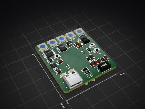

It measures 80 × 60 mm and has 2 copper layers, 1.6 mm thick.
69 parts, built around the DRV8833PWPR, AP63203WU, CH224K and MT3608L. The full list of its parts is on this page, with links to each part's symbol and footprint where PCBKit's library has them.
From the TTembe/EEE3088F_2025 repository on GitHub, at the commit this page was made from: the board is project/project.kicad_pcb and its schematic project/Electro/Electro.kicad_sch. PCBKit opens the board in the browser, with nothing to install.
Its repository states no licence, so its author keeps all rights: ask TTembe before reusing the design.