Bloopy 🤖
An AI Companion Robot Prototype
Designed and built by Brandon Carmona Guerena
Bloopy is a personal robotics project exploring how electronics,
physical interaction, and artificial intelligence can work together
to create a more expressive companion.
The project began with an idea: What if a digital companion could
eventually have a physical presence and interact with its surroundings?
I developed a stationary working prototype to explore that idea,
combining custom hardware, sensors, a Raspberry Pi, an ESP32,
animated eyes, and an AI-assisted companion application.
What the Prototype Does
The stationary Bloopy prototype integrates:
- ESP32: Collects sensor readings and controls OLED eye animations.
- Raspberry Pi 4: Handles higher-level processing and connected peripherals.
- Sensors: Detect environmental conditions and nearby objects.
- OLED eyes: Display expressions and animations in response to interactions.
- Camera and microphone: Support visual and audio input.
- Speaker: Provides audio output.
- Companion application: Provides controls, displays information, and
communicates with the robot.
- AI API integration: Supports context-aware companion responses.
The application and hardware communicate to create an interactive
experience rather than a standalone chatbot.
My Design and Building Process
I developed Bloopy through an iterative process involving:
- Planning the robot's capabilities and component architecture.
- Designing a stationary stand using Fusion 360.
- Designing custom printed circuit boards using KiCad.
- Assembling and connecting electronic components.
- Integrating the ESP32 and Raspberry Pi.
- Developing and refining software with AI assistance.
- Testing the hardware and troubleshooting connections and behavior.
One of the greatest challenges was integrating hardware and software
into a system that behaved as intended.
Custom PCB Designs
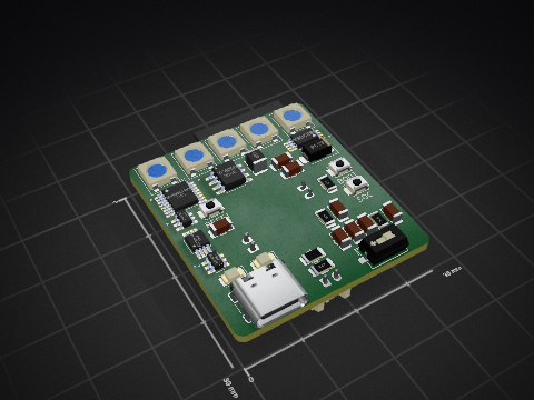
I designed two different PCBs:
BloopyPrototype — Triangular PCB
Created for the stationary prototype.
This board was assembled and used successfully in the working prototype.
BloopyHardware — Rectangular PCB
Designed for a proposed future mobile Bloopy design.
The board was manufactured but has not been assembled or validated
as a working electronic system.
The two designs represent different stages of development,
not two completed robots.
3D-Printed Stand
BloopyPrototype.3mf
The stand was designed in Fusion 360 to support the stationary
robot prototype and its components.
It represents the physical structure used during prototype development.
Repository Structure
Bloopy-App-Reconstructed/
Recovered and reconstructed application source files.
These files document application structure and development work.
They should not be interpreted as a byte-for-byte copy of every
file used in the original running application.
Arduino-Uno-R3/
Reconstructed Arduino Uno R3 example code based on the project's
documented behavior.
The original project used an ultrasonic distance sensor,
a keypad, and an LCD display.
PCB-Additional-Schematics/
Original KiCad design resources for both custom PCB projects.
Each PCB project includes:
.kicad_pcb — PCB layout.kicad_sch — Circuit schematic.kicad_pro — KiCad project settings
BloopyPrototype.3mf
Original 3D CAD model of the stationary Bloopy stand.
SOURCE_NOTES.md
Additional information about source recovery, reconstruction,
and the status of the uploaded files.
Arduino Projects: Where My Electronics Journey Began
Before Bloopy, I learned foundational electronics and programming
through an Arduino course.
After completing the course, I independently adapted earlier code
examples to combine:
- An Arduino Uno R3
- An ultrasonic distance sensor
- An LCD display
- A keypad
The program displayed sensor measurements in the serial monitor
and keypad input on the LCD.
I also attempted a larger Arduino Mega project with multiple sensors.
That second project was unsuccessful because of difficulties with
soldering and electrical connections. Although I did not finish it,
the experience motivated me to learn better assembly techniques.
These experiences helped me understand how individual electronic
components communicate and function together.
Development Tools
- Fusion 360 — Mechanical CAD
- KiCad — PCB and schematic design
- Arduino IDE — Microcontroller development
- ESP32 — Embedded hardware control
- Raspberry Pi — Computing and peripheral integration
- Python and web development technologies
- AI-assisted software development tools
AI Assistance and Source Transparency
I used AI tools, including Claude, to assist with portions of
software development.
My role included defining requirements, specifying behavior,
reviewing generated implementations, requesting changes,
integrating components, and troubleshooting the system.
Some software in this repository was reconstructed after the
original development process. Reconstructed files are identified
as such and should not be represented as the exact original
deployed source code.
The original ESP32 firmware used in the working prototype is
not included in this recovered source collection.
For details, see SOURCE_NOTES.md.
Current Status and Future Goals
Completed: Functional stationary Bloopy prototype integrating
custom electronics, sensors, animated eyes, Raspberry Pi processing,
and a companion application.
Future development: Improving physical expressiveness,
exploring mobility, and developing more continuous character
animations that make Bloopy feel alive.
My long-term goal is to continue learning how mechanical design,
electronics, and software can come together in complete robotic systems.
About the Builder
I'm Brandon Carmona Guerena, a high school student in Phoenix,
Arizona, interested in robotics and engineering.
I enjoy learning by building, experimenting, making mistakes,
and improving my designs.
Visit my GitHub profile