2 layers299 × 82.5 mm
PixelWave
hackclub/OnBoard
💡 Join 1,000 teenagers and make your first PCB with a $100 grant!
663 parts915
 rayvburn/diff_drive_mapping_robot27
ROS driver for the Raspberry Pi based differential drive robot
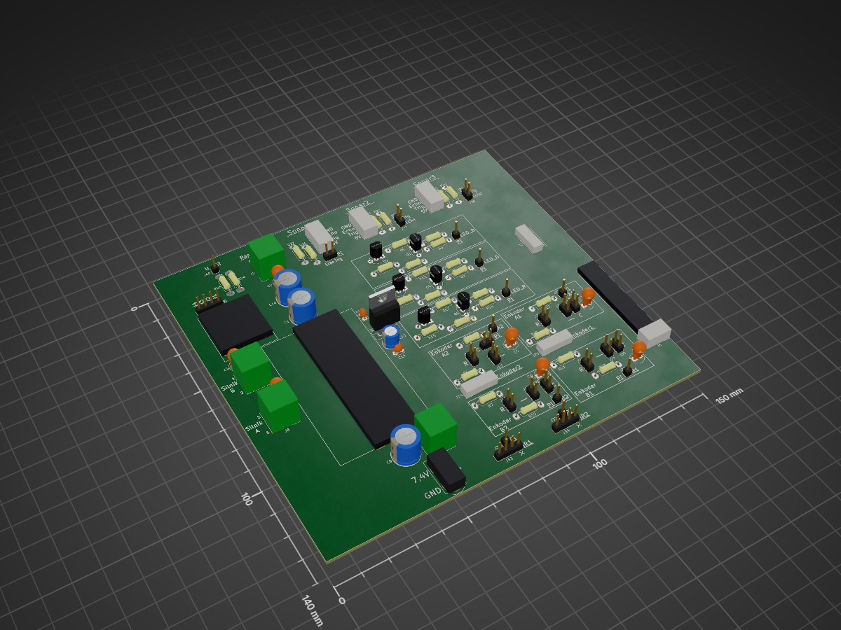
Robot MGR is an open-source printed circuit board by rayvburn, from the rayvburn/diff_drive_mapping_robot repository on GitHub. It is a 2-layer board with 95 parts on 62 nets, routed with 541 tracks and 0 vias.
It is built around the XL4016E1, LD1117S33TR(MS) and MX1508. Its parts include 40 connectors, 31 resistors, 14 capacitors, 6 transistors and 1 IC. It belongs with the robots and motor control boards of this library.


This is the ROS driver for the Raspberry Pi based differential drive robot that was built as a part of my MSc thesis.
Base of the robot was made of acrylic glass. The locomotion is provided by 3 wheels, including 1 caster. The two-wheel differential drive based on DC motors makes the machine nonholonomic.
Within the electronic part of the robot's construction, a printed circuit board was designed. All the necessary electronical components including reflective sensors used to measure the distance from obstacles were placed on the board. The sensor providing the largest amount of data is the camera. It is integrated with the Raspberry Pi microcomputer. The extension of the microcomputer's tasks to the reading of wheel positions and motor control allowed to use its resources efficiently and to avoid adding an extra microcontroller.
Looking at the PCB project (made in KiCad) should give you some idea what components to use if you plan to make a copy of it.
The robot is intended to work together with remote machine like PC that performs some more sophisticated duties. It was created to interface with ORB-SLAM2 well.
The package contents should be placed and compiled both on PC and on RPi's SD card. It was tested only on ROS Kinetic (running on Ubuntu 16.04).
wiringPi library is needed (http://wiringpi.com/). A script to install it on Raspberry Pi was provided.
raspicam_node (https://github.com/UbiquityRobotics/raspicam_node) is required if you will use Raspberry Pi camera but isn't marked as dependency for the package. If you don't plan to use it, just remove appropriate line in robot/robot_offline .launch file (the one with inclusion of raspicam_node's .launch).
If a Raspberry Pi is present within a local Wi-Fi network
roslaunch diff_drive_mapping_robot robot.launchor for testing purposes (no RPi)
roslaunch diff_drive_mapping_robot robot_offline.launchI highly recommend acquiring an Ubuntu image adequate for Raspberry Pi (with ROS Kinetic already installed) from here: https://downloads.ubiquityrobotics.com/pi.html
| Qty | Value | Footprint | References |
|---|---|---|---|
| 12 | Zworka | Pin_Headers:Pin_Header_Straight_1x02_Pitch2.54mm | J15, J16, J17, J18, J19, J20, J23, J24, J26, J27, J29, J30 |
| 11 | 1k | Resistors_THT:R_Axial_DIN0207_L6.3mm_D2.5mm_P10.16mm_Horizontal | R4, R11, R16, R18, R19, R22, R23, R25, R26, R28, R30 |
| 6 | 10k | Resistors_THT:R_Axial_DIN0207_L6.3mm_D2.5mm_P10.16mm_Horizontal | R1, R3, R8, R10, R13, R15 |
| 4 | 2,2k | Resistors_THT:R_Axial_DIN0207_L6.3mm_D2.5mm_P10.16mm_Horizontal | R6, R7, R20, R21 |
| 4 | 20 nF | Capacitors_THT:CP_Radial_Tantal_D5.0mm_P2.50mm | C5, C6, C7, C8 |
| 4 | 2k | Resistors_THT:R_Axial_DIN0207_L6.3mm_D2.5mm_P10.16mm_Horizontal | R24, R27, R29, R31 |
| 3 | 1000 uF / 25V | Capacitors_THT:CP_Radial_D10.0mm_P5.00mm | C1, C9, C10 |
| 3 | 100R | Resistors_THT:R_Axial_DIN0207_L6.3mm_D2.5mm_P10.16mm_Horizontal | R2, R9, R14 |
| 3 | 470 nF / 50V | Capacitors_THT:CP_Radial_Tantal_D5.0mm_P2.50mm | C2, C3, C4 |
| 3 | ???R | Resistors_THT:R_Axial_DIN0207_L6.3mm_D2.5mm_P10.16mm_Horizontal | R5, R12, R17 |
| 3 | Q_NMOS_SGD | TO_SOT_Packages_THT:TO-92_Inline_Wide | Q1, Q4, Q6 |
| 3 | Q_PNP_CBE | TO_SOT_Packages_THT:TO-92_Inline_Wide | Q2, Q5, Q7 |
| 2 | 100nF / 50V | Capacitors_THT:C_Disc_D3.8mm_W2.6mm_P2.50mm | C11, C14 |
| 2 | 33uF / 63V | Capacitors_THT:CP_Radial_D6.3mm_P2.50mm | C12, C13 |
| 1 | Akumulator | XT60:XT60 | J4 |
| 1 | Akumulator_BM | Connectors_JST:JST_XH_B03B-XH-A_03x2.50mm_Straight | J6 |
| 1 | DiodaB_RPi | Pin_Headers:Pin_Header_Straight_1x01_Pitch2.54mm | J3 |
| 1 | DiodaG_RPi | Pin_Headers:Pin_Header_Straight_1x01_Pitch2.54mm | J7 |
| 1 | DiodaRGB | Connectors_JST:JST_EH_B04B-EH-A_04x2.50mm_Straight | J1 |
| 1 | DiodaR_RPi | Pin_Headers:Pin_Header_Straight_1x01_Pitch2.54mm | J10 |
| 1 | Enkoder1 | Connectors_JST:JST_EH_B04B-EH-A_04x2.50mm_Straight | J25 |
| 1 | Enkoder2 | Connectors_JST:JST_EH_B04B-EH-A_04x2.50mm_Straight | J14 |
| 1 | EnkoderA1_RPi | Pin_Headers:Pin_Header_Straight_1x01_Pitch2.54mm | J21 |
| 1 | EnkoderA2_RPi | Pin_Headers:Pin_Header_Straight_1x01_Pitch2.54mm | J5 |
| 1 | EnkoderB1_RPi | Pin_Headers:Pin_Header_Straight_1x01_Pitch2.54mm | J22 |
| 1 | EnkoderB2_RPi | Pin_Headers:Pin_Header_Straight_1x01_Pitch2.54mm | J12 |
| 1 | HBridgeInputs | Pin_Headers:Pin_Header_Straight_1x04_Pitch2.54mm | J28 |
| 1 | HX-2S-01_5A | HX-2S-01_5A:HX-2S-01_5A | BMS1 |
| 1 | IR1 | Pin_Headers:Pin_Header_Straight_1x04_Pitch2.54mm | J33 |
| 1 | IR1_Out_RPi | Pin_Headers:Pin_Header_Straight_1x01_Pitch2.54mm | J31 |
| 1 | IR2 | Pin_Headers:Pin_Header_Straight_1x04_Pitch2.54mm | J34 |
| 1 | IR2_Out_RPi | Pin_Headers:Pin_Header_Straight_1x01_Pitch2.54mm | J32 |
| 1 | LD1117S33TR | TO_SOT_Packages_THT:TO-220-3_Vertical | U1 |
| 1 | MX1508 | MX1508:MX1508 | HBridge1 |
| 1 | MotorA | TerminalBlock_Philmore:TerminalBlock_Philmore_TB132_02x5mm_Straight | J8 |
| 1 | MotorB | TerminalBlock_Philmore:TerminalBlock_Philmore_TB132_02x5mm_Straight | J9 |
| 1 | NapiecieAkumulatora_RPi | Pin_Headers:Pin_Header_Straight_1x01_Pitch2.54mm | J40 |
| 1 | SonarRAW1 | Connectors_JST:JST_XH_B04B-XH-A_04x2.50mm_Straight | J13 |
| 1 | SonarRAW2 | Connectors_JST:JST_XH_B04B-XH-A_04x2.50mm_Straight | J35 |
| 1 | SonarRAW3 | Connectors_JST:JST_XH_B04B-XH-A_04x2.50mm_Straight | J36 |
| 1 | SonarRPi1 | Pin_Headers:Pin_Header_Straight_1x02_Pitch2.54mm | J39 |
| 1 | SonarRPi2 | Pin_Headers:Pin_Header_Straight_1x02_Pitch2.54mm | J37 |
| 1 | SonarRPi3 | Pin_Headers:Pin_Header_Straight_1x02_Pitch2.54mm | J38 |
| 1 | WylacznikGlowny | TerminalBlock_Philmore:TerminalBlock_Philmore_TB132_02x5mm_Straight | J11 |
| 1 | XL4016 | XL4016:XL4016 | BuckConverter1 |
| 1 | ZasilanieRaspberry | TerminalBlock_Philmore:TerminalBlock_Philmore_TB132_02x5mm_Straight | J2 |
95 parts, built around the XL4016E1, LD1117S33TR(MS) and MX1508. The full list of its parts is on this page, with links to each part's symbol and footprint where PCBKit's library has them.
From the rayvburn/diff_drive_mapping_robot repository on GitHub, at the commit this page was made from: the board is PCB - KiCad/Robot_MGR/Robot_MGR.kicad_pcb. PCBKit opens the board in the browser, with nothing to install.
Its repository states no licence, so its author keeps all rights: ask rayvburn before reusing the design.
hackclub/OnBoard
💡 Join 1,000 teenagers and make your first PCB with a $100 grant!

Ramahabir/6-DOF-Robotics-Arm-Dynamixel
Open-source 6-DOF robot arm controller using STM32F411, Dynamixel servos, custom KiCad PCB, PWM gripper control, data logging, and planned ESP32-C3 wireless communication.

Circuit-Digest/ESP32-Cam-Surveillance-Car
Watch full video on ESP32 surveillance car

shaise/OpenSky328
An atmel implementation of OpenSky FrSky-compatible RX


3stan-H/Bench-Power-Supply
A mains-powered, adjustable bench power supply designed in KiCad, converting 120V AC wall input into a regulated 1–20V DC output.
