2 layers61.8 × 21.6 mm
USBQuadMouse
PR77/CH554_USBQuadMouseKeyboard
CH554 based USB to Quadrature Mouse and Keyboard Interface
24 parts8MIT

 PR77/IoT_Messenger3
IoT Messenger (Pager) For Simple 1 Way Communication
IoT Messenger is an open-source printed circuit board by PR77, from the PR77/IoT_Messenger repository on GitHub, published under the LGPL-3.0 licence. It is a 2-layer board of 76.2 × 46.9 mm with 64 parts on 46 nets, routed with 339 tracks and 61 vias.
It is built around the ESP-12F, DHT11 and LM1117-3.3, with the IRLML6402 and SS16 among its other parts. Its parts include 18 resistors, 16 capacitors, 5 connectors, 4 ICs and 4 switches. It belongs with the home automation and IoT and lEDs and displays boards and the ESP8266 boards of this library.


IoT Messenger (Pager) For Simple 1 Way Communication
This design has not been compliance tested and will not be. It is published purely for inspiration to others. I take no responsibility for damages caused directly or indirectly. I accept no responsibility for any damage to any equipment that results from the use of this design and its components. IT IS ENTIRELY AT YOUR OWN RISK!
As a child growing up in the 80's I have fond memories of old skool pagers and analog mobile phones the size of bricks. I remember buying a bunch of old analog Motorola (R) Brick Phones just before the analog network was shut down and turning them into scanners. This project is in no way connected to that, but the fond memory of pagers is something I wanted to bing back with this project. In addition to this, my other motivation for the project was it's "semi" practical use as a real pager within a known WiFi network.
My IoT Messenger is essentially some common components connected to an ESP8266, ESP12-F to be specific. However, it is the form factor and user interface which draws parallels to a pager. It is my first revision of the project and has a lot fo fine tuning - should I or the community want to pursue it further. I would like to continue improving this as I see it would be fun for those who use it.
Interfacing with the device is via the Web using the simple HTTP Server class. The IoT Messenger sends out a webpage where the message and other functions can be accessed. As my HTML and JS skills are not up there, I have resorted to using CURL during development and debugging - HELP NEEDED! :)
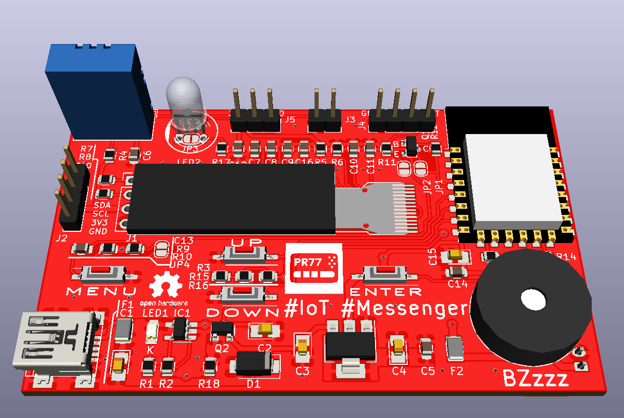
Here is a nice 3d model of the PCB;
Nice 3D model:
My IoT Messenger needs to be portable therefore battery power and a basic set of controls are essential. I use a 600 mA LiPo cell which is charged via USB. USB provides power only. No intelligent power management has been implemented yet, so when running only via battery it last 4 - 5 hours.
There are 4 buttons for user input which can also be used for additional functions (see how Tetris and Dino game use them).
I use the MCP73831 LiPo battery charger with a P-Channel load balancing FET. This is to ensure the LiPo charger only charges the battery when connected to a USB power source. The necessary 3.3 volts is obtained via a basic LM1117-3.3.
I wanted to have the PCB somewhat universal - I guess like an evaluation or child friendly development board - so I added a nice RGB LED (PL9823) and an environmental sensor (DHT11). In addition to these, as the device is inspired by pagers, it has a OLED display (128x32) and Piezo Beeper.
As mentioned, flexibility was important so with the OLED, it is essentially dual-footprinted where a module with necessary passives could just be solder on, or the raw OLED panel and necessary passives be soldered on the IoT Messenger board. For my prototype I used the latter so get some experience with this. Lastly, I added a SAO port, well for - Add Ons.
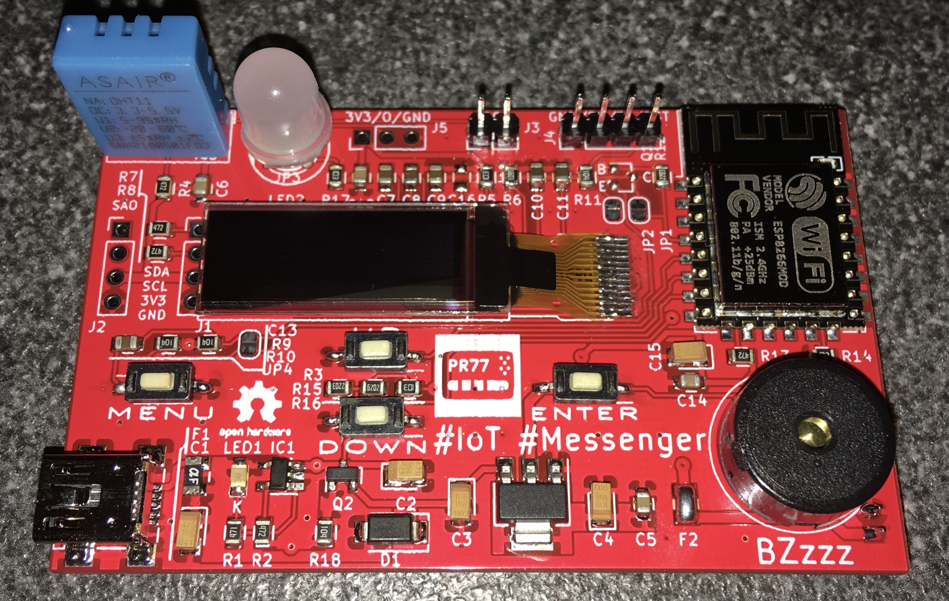
Nice fully soldered IoT Messenger:
All of the interfacing with the hardware features is via HTTP Server GET and POST requests. The following services have been implemented currently;
| Request | Type | Parameters | Comments |
|---|---|---|---|
| /list | GET | none | Lists files currently saved to SPIFFS |
| /upload | POST | filename | Uploads a file to SPIFFS |
| /format | POST | none | Formats SPIFFS |
| /info | GET | none | Get SPIFFS and CPU MHz info |
| /sensor | GET | none | Read environmental sensor data (DHT11) |
| /message | POST | text | Write a message to the buffer |
| /led | POST | colour | Set RGB LED colour |
| /beeper | POST | count | Beep piezo beeper |
Of course. Check out my IoT Messenger playing the Tetris game theme music or Dino Jump. Videos are in the Images folder.
PlatformIO is the main development environment. In addition to the Arduino framework for ESP8266, I used the following (either important as libraries into PIO or seperate);
| Qty | Value | Footprint | References |
|---|---|---|---|
| 5 | 1uF | Capacitors_SMD:C_0805 | C7, C8, C9, C13, C16 |
| 4 | 100K | Resistors_SMD:R_0805 | R9, R10, R11, R18 |
| 4 | 100nF | Capacitors_SMD:C_0805 | C5, C6, C12, C14 |
| 4 | 10K | Resistors_SMD:R_0805 | R5, R14, R16, R17 |
| 4 | 4K7 | Resistors_SMD:R_0805 | R4, R7, R8, R13 |
| 3 | 10uF | Capacitors_Tantalum_SMD:CP_Tantalum_Case-R_EIA-2012-12_Reflow | C3, C4, C15 |
| 2 | 4.7uF | Capacitors_Tantalum_SMD:CP_Tantalum_Case-R_EIA-2012-12_Reflow | C1, C2 |
| 2 | 4.7uF | Capacitors_SMD:C_0805 | C10, C11 |
| 2 | 500mA | Fuse_Holders_and_Fuses:Fuse_SMD1206_Reflow | F1, F2 |
| 1 | 220K | Resistors_SMD:R_0805 | R3 |
| 1 | 2K | Resistors_SMD:R_0805 | R2 |
| 1 | 330K | Resistors_SMD:R_0805 | R12 |
| 1 | 470R | Resistors_SMD:R_0805 | R1 |
| 1 | 560K | Resistors_SMD:R_0805 | R6 |
| 1 | 62K | Resistors_SMD:R_0805 | R15 |
| 1 | BATT | Connectors_JST:JST_PH_S2B-PH-K_02x2.00mm_Angled | CONN2 |
| 1 | Buzzer | Buzzers_Beepers:Buzzer_15x7.5RM7.6 | BZ1 |
| 1 | DBNC | KiCad-Jumper:SolderJumper-2_P1.3mm_Open_RoundedPad1.0x1.5mm | JP4 |
| 1 | DHT11 | KiCad-Sensors:Aosong_DHT11_5.5x12.0_P2.54mm | IC3 |
| 1 | DISP2 | Pin_Headers:Pin_Header_Straight_1x04_Pitch2.54mm | J1 |
| 1 | DOWN | Buttons_Switches_SMD:SW_DIP_x1_W7.62mm_Slide_Copal_CHS-B | SW3 |
| 1 | ENTER | Buttons_Switches_SMD:SW_DIP_x1_W7.62mm_Slide_Copal_CHS-B | SW4 |
| 1 | ESP-12F | RF_Modules:ESP-12E | IC4 |
| 1 | I2C | Pin_Headers:Pin_Header_Straight_1x04_Pitch2.54mm | J2 |
| 1 | IRLML6402 | TO_SOT_Packages_SMD:SOT-23 | Q2 |
| 1 | LED | KiCad-Jumper:SolderJumper-2_P1.3mm_Open_RoundedPad1.0x1.5mm | JP3 |
| 1 | LED | LEDs:LED_0805 | LED1 |
| 1 | LED | Pin_Headers:Pin_Header_Straight_1x03_Pitch2.54mm | J5 |
| 1 | LM1117-3.3 | TO_SOT_Packages_SMD:SOT-223-3_TabPin2 | IC2 |
| 1 | LOGO | IoT_Messenger:Logo | G*** |
| 1 | MCP73831-2-OT | TO_SOT_Packages_SMD:SOT-23-5_HandSoldering | IC1 |
| 1 | MENU | Buttons_Switches_SMD:SW_DIP_x1_W7.62mm_Slide_Copal_CHS-B | SW1 |
| 1 | PL9823 | LEDs:LED_D5.0mm-4-STEPPED | LED2 |
| 1 | PROG | Pin_Headers:Pin_Header_Straight_1x02_Pitch2.54mm | J3 |
| 1 | Q_NPN_BEC | TO_SOT_Packages_SMD:SOT-23 | Q1 |
| 1 | Reset | KiCad-Jumper:SolderJumper-2_P1.3mm_Open_RoundedPad1.0x1.5mm | JP2 |
| 1 | SERIAL | Pin_Headers:Pin_Header_Straight_1x04_Pitch2.54mm | J4 |
| 1 | SS16 | Diodes_SMD:D_SMA | D1 |
| 1 | SSD1306 | KiCad-SSD1306:SSD1306_OLED-0.91-128x32 | DISP1 |
| 1 | UP | Buttons_Switches_SMD:SW_DIP_x1_W7.62mm_Slide_Copal_CHS-B | SW2 |
| 1 | USB_B_Micro | Connectors:USB_Mini-B | CONN1 |
| 1 | WakeUP | KiCad-Jumper:SolderJumper-2_P1.3mm_Open_RoundedPad1.0x1.5mm | JP1 |
The 63 most common of 64 parts.
It measures 76.2 × 46.9 mm and has 2 copper layers, 1.6 mm thick.
64 parts, built around the ESP-12F, DHT11, LM1117-3.3 and IRLML6402. The full list of its parts is on this page, with links to each part's symbol and footprint where PCBKit's library has them.
From the PR77/IoT_Messenger repository on GitHub, at the commit this page was made from: the board is Hardware/IoT_Messenger.kicad_pcb. PCBKit opens the board in the browser, with nothing to install.
Its repository publishes it under the LGPL-3.0 licence: you may reuse it on that licence's terms (keep the author's notice, and for a copyleft licence share your changes alike).
PR77/CH554_USBQuadMouseKeyboard
CH554 based USB to Quadrature Mouse and Keyboard Interface


ViktorStiskala/ESP8266-door-sensor
This design represents a small sensor intended to be triggered by a magnetic reed switch. It wakes upon closing the contact, reporting the information to the internet and going back to sleep.

TeFka/PeatMonitoringProject
This is the repository for used for storage of all software code and other components produced during the project of developing the peat monitoring device or University of Nottingham EEEE4019 Group Project.

Pablo-Ortiz-Lopez/ClimateController
ESP8266 based device which handles the climate of a room.


greenMikeEU/shrdzm
SHRDZM (just a name, not an acronym) is an ESP8285/ESP8266 based sensor and actor integration platform.