2 layers107.7 × 49.8 mm
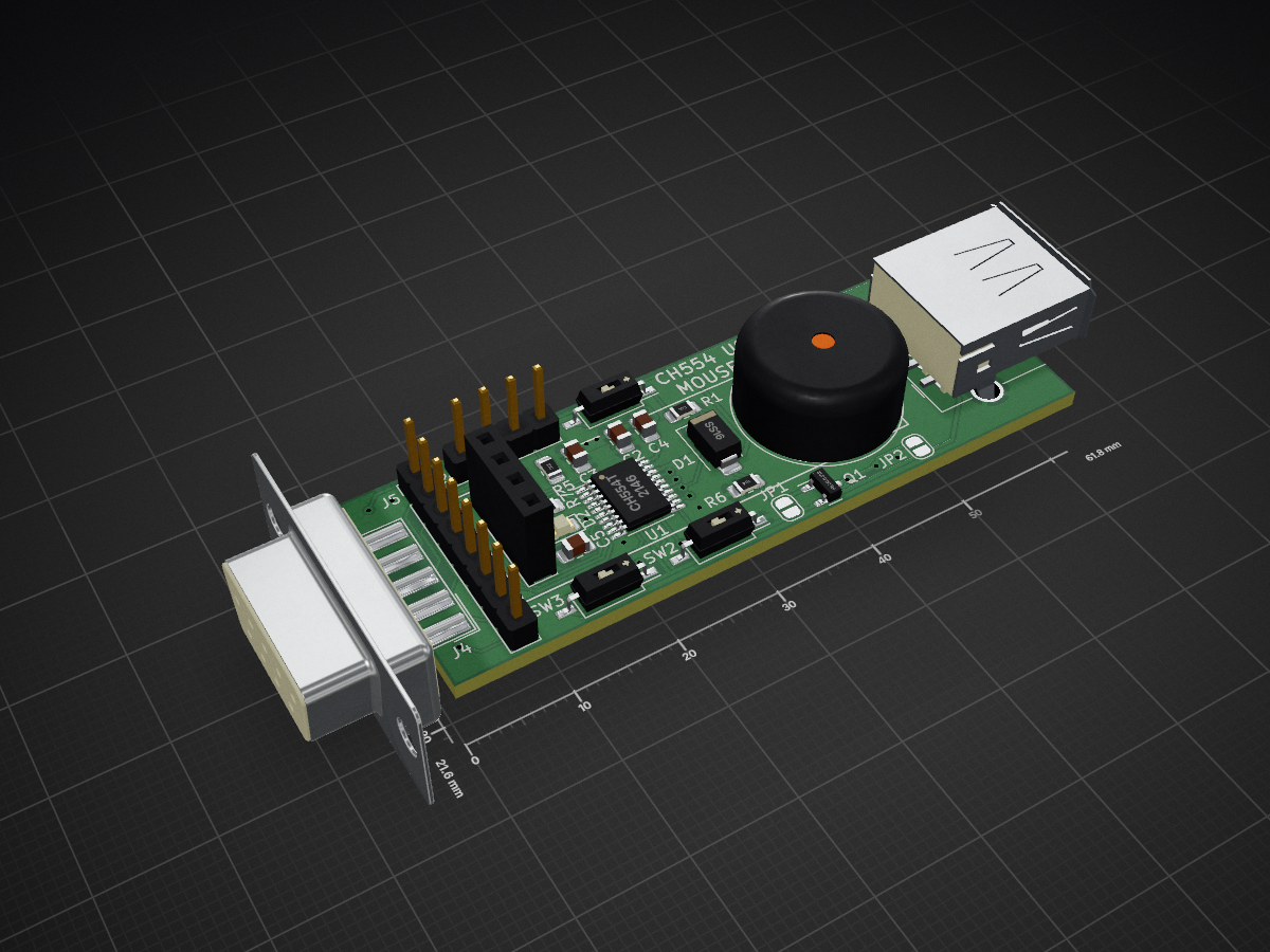
 PR77/CH554_USBQuadMouseKeyboard8
CH554 based USB to Quadrature Mouse and Keyboard Interface
USBQuadMouse is an open-source printed circuit board by PR77, from the PR77/CH554_USBQuadMouseKeyboard repository on GitHub, published under the MIT licence. It is a 2-layer board of 61.8 × 21.6 mm with 24 parts on 28 nets, routed with 284 tracks and 23 vias.
It is built around the CH554T, IRLML6402 and SS16. Its parts include 5 resistors, 5 connectors, 4 capacitors, 3 switches and 2 diodes. It belongs with the keyboards and input and retro computing and games boards and the 8051 (CH55x, STC, AT89) boards of this library.


USB MOUSE + KEYBOARD <-> AMIGA X-LATER based on the WCH554 MCS51 based chip with USB Device + Host Interface.
This design has not been compliance tested and will not be. It may cause personal damage to you or others. I take no responsibility for this. I accept no responsibility for any damage to any equipment that results from the use of this design and its components. IT IS ENTIRELY AT YOUR OWN RISK!
This project allows you to use a USB mouse or keyboard on an Amiga computer - of course only one-or-the-other is supported at any one time. It essentially converts a USB mouse to generate a quadrature signal stream, similarly it converts a USB keyboard keycodes (currently only DE is implemented) to work with an Amiga. There are many variants of such a project available, either using this micro controller or others, however I'm using this project as an opportunity to learn more about the WCH55x micro controller.
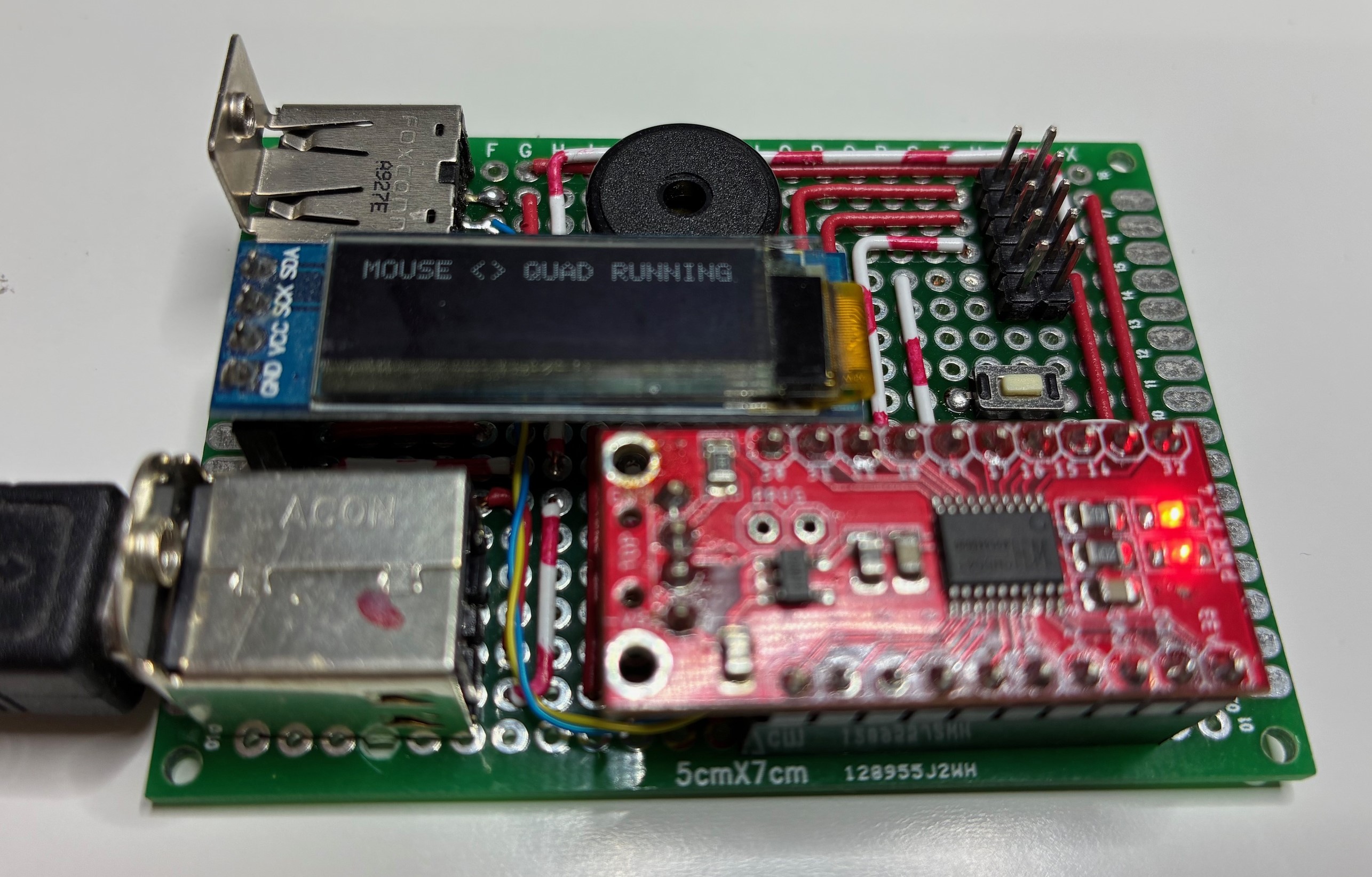
I forgot to take a picture of the mess of wires breadboard version, so here is a picture on some perf-board instead. I'm using the USB B socket for debugging and the USB A socket is for the Mouse Connection. Of course only 1 device (either PC for debugging or Mouse for using) can be connected. I got the two USB sockets from an old printer board I found lying around the house.
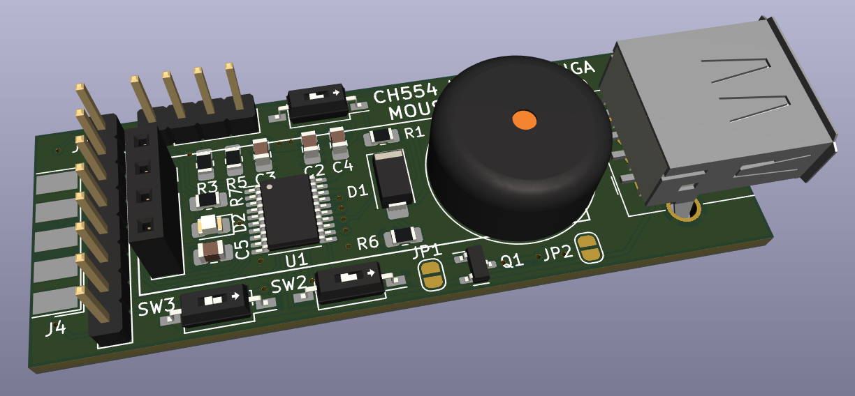
PCB version has been routed and manufactured for supporting a mouse or keyboard. Here is the usual 3D artwork of the design.
OLED is also supported so you can see some information for example keyboard and mouse report data.
I refacted a lot of the original libraries into various software components. However there were some repos which provided me with excellent information, tools and resources;
| Qty | Value | Footprint | References |
|---|---|---|---|
| 4 | 100N | Capacitor_SMD:C_0805_2012Metric_Pad1.18x1.45mm_HandSolder | C2, C3, C4, C5 |
| 2 | 10R | Resistor_SMD:R_0805_2012Metric_Pad1.20x1.40mm_HandSolder | R3, R5 |
| 1 | 100K | Resistor_SMD:R_0805_2012Metric_Pad1.20x1.40mm_HandSolder | R6 |
| 1 | 10K | Resistor_SMD:R_0805_2012Metric_Pad1.20x1.40mm_HandSolder | R1 |
| 1 | 1K | Resistor_SMD:R_0805_2012Metric_Pad1.20x1.40mm_HandSolder | R7 |
| 1 | 5V | Jumper:SolderJumper-2_P1.3mm_Open_RoundedPad1.0x1.5mm | JP2 |
| 1 | AmigaKeyboard | Connector_PinHeader_2.54mm:PinHeader_1x08_P2.54mm_Vertical | J5 |
| 1 | AmigaMouse | Connector_Dsub:DSUB-9_Female_EdgeMount_P2.77mm | J4 |
| 1 | Buzzer | Buzzer_Beeper:Buzzer_15x7.5RM7.6 | BZ1 |
| 1 | CH554T | Package_SO:TSSOP-20_4.4x6.5mm_P0.65mm | U1 |
| 1 | IRLML6402 | Package_TO_SOT_SMD:SOT-23 | Q1 |
| 1 | LED | LED_SMD:LED_0805_2012Metric_Pad1.15x1.40mm_HandSolder | D2 |
| 1 | OLED | Connector_PinSocket_2.54mm:PinSocket_1x04_P2.54mm_Vertical | J6 |
| 1 | SS16 | Diode_SMD:D_SMA | D1 |
| 1 | SW_BOOT | Button_Switch_SMD:SW_DIP_SPSTx01_Slide_Copal_CHS-01B_W7.62mm_P1.27mm | SW1 |
| 1 | SW_BOOTLOADER | Button_Switch_SMD:SW_DIP_SPSTx01_Slide_Copal_CHS-01B_W7.62mm_P1.27mm | SW2 |
| 1 | SW_RESET | Button_Switch_SMD:SW_DIP_SPSTx01_Slide_Copal_CHS-01B_W7.62mm_P1.27mm | SW3 |
| 1 | Serial | Connector_PinHeader_2.54mm:PinHeader_1x04_P2.54mm_Vertical | J2 |
| 1 | USB_A | Connector_USB:USB_A_Molex_67643_Horizontal | J3 |
| 1 | VBUS | Jumper:SolderJumper-2_P1.3mm_Open_RoundedPad1.0x1.5mm | JP1 |


PR77/IoT_Messenger
IoT Messenger (Pager) For Simple 1 Way Communication

rallepalaveev/A2DVI
This is based on Clintech Pico Board (CPB) with 48 GPIOs, most 5V tolerant.

BerkeleyLab/Marble
Dual FMC FPGA carrier board developed for general purpose use in particle accelerator electronics instrumentation.

andrekuehne/openradfan
An ESPHome-driven controller for radiator fans to improve heat output

BerkeleyLab/Marble-Mini
"Marble-Mini" Simple FMC carrier board with SFP, 2x FMC, PoE

It measures 61.8 × 21.6 mm and has 2 copper layers, 1.6 mm thick.
24 parts, built around the CH554T, IRLML6402 and SS16. The full list of its parts is on this page, with links to each part's symbol and footprint where PCBKit's library has them.
From the PR77/CH554_USBQuadMouseKeyboard repository on GitHub, at the commit this page was made from: the board is Hardware/USBQuadMouse.kicad_pcb and its schematic Hardware/USBQuadMouse.kicad_sch. PCBKit opens the board in the browser, with nothing to install.
Its repository publishes it under the MIT licence: you may reuse it on that licence's terms (keep the author's notice, and for a copyleft licence share your changes alike).