4 layers63.8 × 50.8 mm
V2 reference
ameesme/little-camera
A small black-and-white camera that posts to its own tiny blog, and everything around it.
85 partsMIT

 PHS-SMCS/falcon-core
Lightest ESP32-based blimp controller with the works; 9-DoF, ToF altimetry, motor drivers, and Wi-Fi enabled camera streaming, all on a single 300mAh LiPo. >1hr of battery life.
Falcon core is an open-source printed circuit board by PHS-SMCS, from the PHS-SMCS/falcon-core repository on GitHub, published under the AGPL-3.0 licence. It is a 4-layer board of 32 × 46 mm with 94 parts on 90 nets, routed with 928 tracks and 218 vias.
It is built around the ESP32-S3-WROOM-1-N8, DRV8212PDSG and TPS63001DRC, with the ME6211C28M5G-N, BMI270 and ME6211C12M5G-N among its other parts. Its parts include 34 capacitors, 20 resistors, 13 ICs, 4 diodes and 3 connectors. It belongs with the radio and wireless and robots and motor control boards and the ESP32 boards of this library.


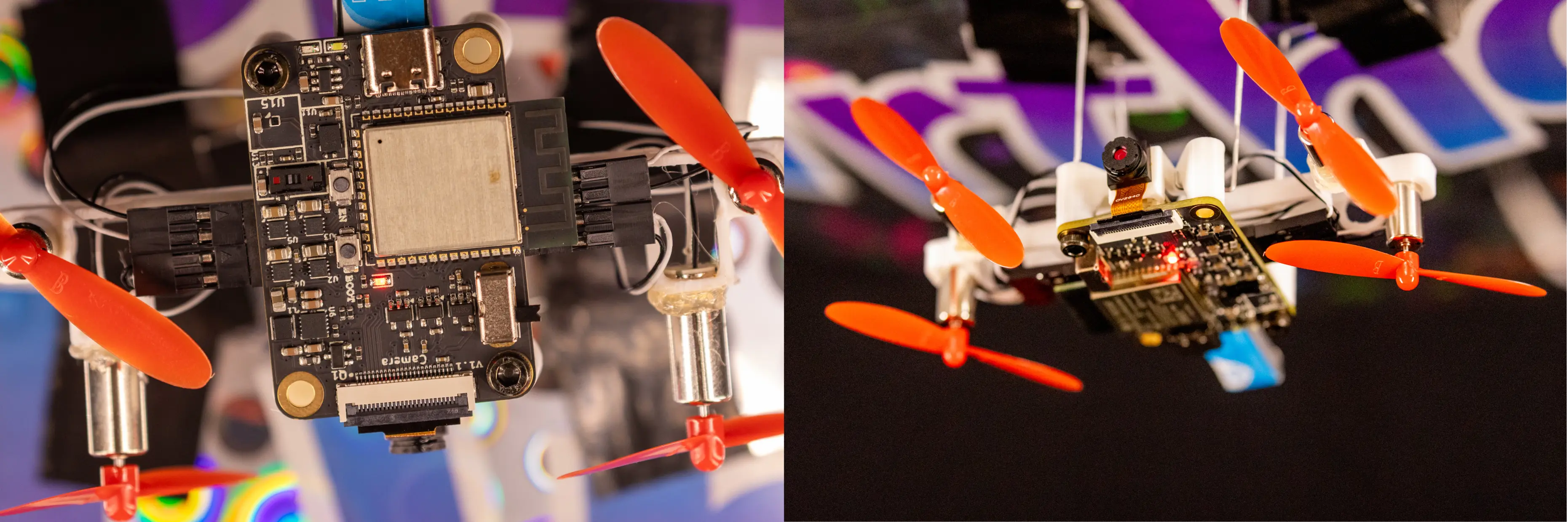
A custom standalone ESP32-S3 flight controller for an indoor autonomous blimp. Successor to Falcon Flight, redesigned from a Raspberry Pi Zero 2W HAT into a purpose-built 32×46mm 4-layer PCB.
Sponsored by PCBWay.
| GPIO | Function |
|---|---|
| 1, 2 | SCCB (camera I2C — SIOD, SIOC) |
| 3 | M2_IN1 |
| 4 | M3_IN2 |
| 5 | M3_IN1 |
| 6 | M1_IN2 |
| 7 | BAT_ADC (battery voltage sensing) |
| 8, 18 | Main I2C bus (SDA, SCL) |
| 9, 10, 11, 12, 13, 14, 21, 40 | OV2640 DVP data bus (D8, D7, D6, D2, D5, D3, D4, D9) |
| 15 | M4_IN1 |
| 16 | M4_IN2 |
| 17 | M2_IN2 |
| 19, 20 | USB D−/D+ |
| 38 | Camera PCLK |
| 39 | Camera XCLK |
| 41 | HREF |
| 42 | VSYNC |
| 43, 44 | UART0 debug |
| 47 | M1_IN1 |
| 48 | Red LED (1kΩ to GND) |
Camera PWDN tied to GND, RESETB tied to 3.3V.
All sensors share the main I2C bus (GPIO8/18):
Camera SCCB runs on a separate bus (GPIO1/2).
Built with ESP-IDF. Custom PID stabilization (no ArduPilot). Communicates with a laptop over WebSocket for optical flow and AprilTag detection via OpenCV.
See LICENSE.
| Qty | Value | Footprint | References |
|---|---|---|---|
| 11 | 100nF | PCM_JLCPCB:C_0402 | C17, C19, C20, C21, C22, C23, C28, C29, C30, C31, C36 |
| 9 | 10uF | PCM_JLCPCB:C_0603 | C9, C10, C11, C12, C13, C14, C18, C33, C34 |
| 8 | 1uF | PCM_JLCPCB:C_0402 | C1, C2, C3, C4, C5, C6, C7, C30 |
| 6 | 47uF | PCM_JLCPCB:C_0805 | C24, C25, C26, C27, C32, C35 |
| 5 | 100kΩ | PCM_JLCPCB:R_0402 | R1, R2, R9, R12, R13 |
| 4 | 47kΩ | PCM_JLCPCB:R_0402 | R14, R15, R16, R17 |
| 4 | 5.1kΩ | PCM_JLCPCB:R_0402 | R5, R6, R18, R19 |
| 4 | DRV8212P | Package_SON:WSON-8-1EP_2x2mm_P0.5mm_EP0.9x1.6mm_ThermalVias | U2, U3, U4, U5 |
| 4 | MountingHole | MountingHole:MountingHole_3.2mm_M3_DIN965_Pad | H1, H2, H3, H4 |
| 3 | 1kΩ | PCM_JLCPCB:R_0402 | R7, R8, R20 |
| 2 | 2.2kΩ | PCM_JLCPCB:R_0402 | R3, R11 |
| 2 | Conn_01x04_Socket | JLCPCB_GLOBAL_Footprints:CONN-SMD_4P-P2.54_HX-PM2.54-1X4PWT | J3, J4 |
| 2 | ME6211C28M5 | Package_TO_SOT_SMD:SOT-23-5 | U8, U10 |
| 2 | Red | PCM_JLCPCB:D_0603 | D1, D4 |
| 2 | Tactile Button, 160gf | PCM_JLCPCB:SW_TS-1088-AR02016 | S1, S2 |
| 1 | 100Ω | PCM_JLCPCB:R_0402 | R4 |
| 1 | 1V2 | TestPoint:TestPoint_Pad_D2.0mm | TP6 |
| 1 | 2.2uH | Inductor_SMD:L_APV_ANR252010 | L1 |
| 1 | 2kΩ | PCM_JLCPCB:R_0402 | R10 |
| 1 | 3V3 | TestPoint:TestPoint_Pad_D2.0mm | TP4 |
| 1 | 5V | TestPoint:TestPoint_Pad_D2.0mm | TP10 |
| 1 | AO3401A | Package_TO_SOT_SMD:SOT-23 | Q1 |
| 1 | BMI270 | BMI270:XDCR_BMI270 | U11 |
| 1 | BOOT | TestPoint:TestPoint_Pad_D2.0mm | TP2 |
| 1 | Conn_01x02 | JLCPCB_Footprints:CONN-SMD_2P-P2.00_WF-1F200A2P | BAT1 |
| 1 | EN | TestPoint:TestPoint_Pad_D2.0mm | TP1 |
| 1 | ESP32-S3-WROOM-1 | RF_Module:ESP32-S3-WROOM-1 | U1 |
| 1 | FPC-05F-24PH20 | JLCPCB_Footprints:FPC-SMD_24P-P0.50_FPC-05F-24PH20 | FPC1 |
| 1 | FerriteBead | Inductor_SMD:L_0603_1608Metric | FB1 |
| 1 | GND | TestPoint:TestPoint_Pad_D2.0mm | TP3 |
| 1 | H7VN10B | PCM_JLCPCB:D_DFN1006-2L | D3 |
| 1 | LOGO | JLCPCB_Footprints:SMCS-Logo | G*** |
| 1 | ME6211C12M5 | Package_TO_SOT_SMD:SOT-23-5 | U9 |
| 1 | MMC5603NJL | Package_BGA:WLP-4_0.86x0.86mm_P0.4mm | U15 |
| 1 | SW_SPDT | Button_Switch_THT:SW_Slide_SPDT_Angled_CK_OS102011MA1Q | SW1 |
| 1 | TP4057 | Package_TO_SOT_SMD:TSOT-23-6 | U7 |
| 1 | TPS63001 | Package_SON:Texas_DRC0010J_ThermalVias | U6 |
| 1 | USB_C_Receptacle_USB2.0_16P | Connector_USB:USB_C_Receptacle_GCT_USB4105-xx-A_16P_TopMnt_Horizontal | J2 |
| 1 | VBUS | TestPoint:TestPoint_Pad_D2.0mm | TP9 |
| 1 | VL53L5CXV0GC_1 | VL53L5:XDCR_VL53L5CXV0GC_1 | U13 |
| 1 | White | PCM_JLCPCB:D_0603 | D2 |
It measures 32 × 46 mm and has 4 copper layers, 1.6 mm thick.
94 parts, built around the ESP32-S3-WROOM-1-N8, DRV8212PDSG, TPS63001DRC and ME6211C28M5G-N. The full list of its parts is on this page, with links to each part's symbol and footprint where PCBKit's library has them.
From the PHS-SMCS/falcon-core repository on GitHub, at the commit this page was made from: the board is PCB/falcon-core.kicad_pcb and its schematic PCB/falcon-core.kicad_sch. PCBKit opens the board in the browser, with nothing to install.
Its repository publishes it under the AGPL-3.0 licence: you may reuse it on that licence's terms (keep the author's notice, and for a copyleft licence share your changes alike).
ameesme/little-camera
A small black-and-white camera that posts to its own tiny blog, and everything around it.


Guilleloma/Furby-GPT
This project transforms a 1998 Furby into an interactive and advanced desktop assistant using a Raspberry Pi W. It incorporates OpenAI and Whisper for natural language processing, primarily relying on Google Cloud Text…


HeyPCB/iris-cortex
Iris Cortex: head controller of the Iris robot head. ESP32-S3 (16 MB flash, 8 MB PSRAM), OV2640 eye-camera FPC, iris-ring LED drivers, harness hub.

OHNope/sc035hgs-esp32-p4x-camera-adapter-mod
本仓库在 ESP32-P4XMIPICameraSubV1.1KiCAD(Espressif 官方相机转接板的 KiCad 转换版)基础上,修改为 SC035HGS 相机模组用的转接板。基础工程(导入修复、检查结果)的说明见它的 README。

