4 layers76 × 54 mm
Pixelblaze battery backpack
SK-Electronics-Consulting/electronics-widgets
Small, Custom Tools for Electronics
112 parts1

 Person-0/Quad0
The board will be designed in a way such that it can fly with standard 8520 coreless motors and a tiny lipo battery for brushed mode.
Quad0 is an open-source printed circuit board by Person-0, from the Person-0/Quad0 repository on GitHub. It is a 4-layer board of 60 × 50 mm with 100 parts on 84 nets, routed with 888 tracks and 116 vias.
It is built around the RP2350A, ESP-01 and BMM150, with the DPS368XTSA1(TOKMAS), W25Q128JVSIQ and ABM8-272-T3 among its other parts. Its parts include 32 capacitors, 25 resistors, 9 ICs, 9 connectors and 6 diodes. It belongs with the ESP8266 and RP2350 boards of this library.


quadcopter with a custom flight controller, firmware that supports both brushed and brushless motors
This is a custom flight controller with minimal stuff required to fly a quadcopter on-board, supporting both brushless and brushed motors.
Onboard components include:
RP2350A Microcontroller Unit
IMU:
ICM-42688-P Accelerometer & GyroscopeDPS368XTSA1 BarometerBMM150 MagnetometerMOSFET motor drivers (DMN2024UFDF-7) for brushed motors
Pads to connect brushed / brushless motors
Support for ESP01 WiFi module for brushed mode OR any radio receiver that supports SBUS or similar protocols for brushless mode
The board will be designed in a way such that it can fly with standard 8520 coreless motors and a tiny lipo battery for brushed mode.
As for the brushless mode, I will be targeting 2204 size brushless motors with a 5inch prop size, ~5inch frame configuration.
For building, skip to Build instructions section.
The PCB 3D preview looks like this:
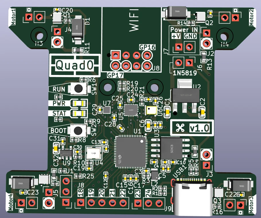
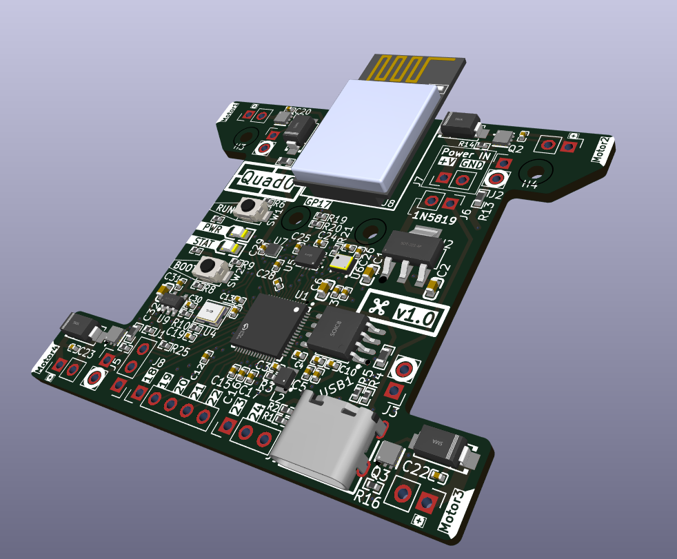
[Right Click >> Open in new tab] on the image to view properly.
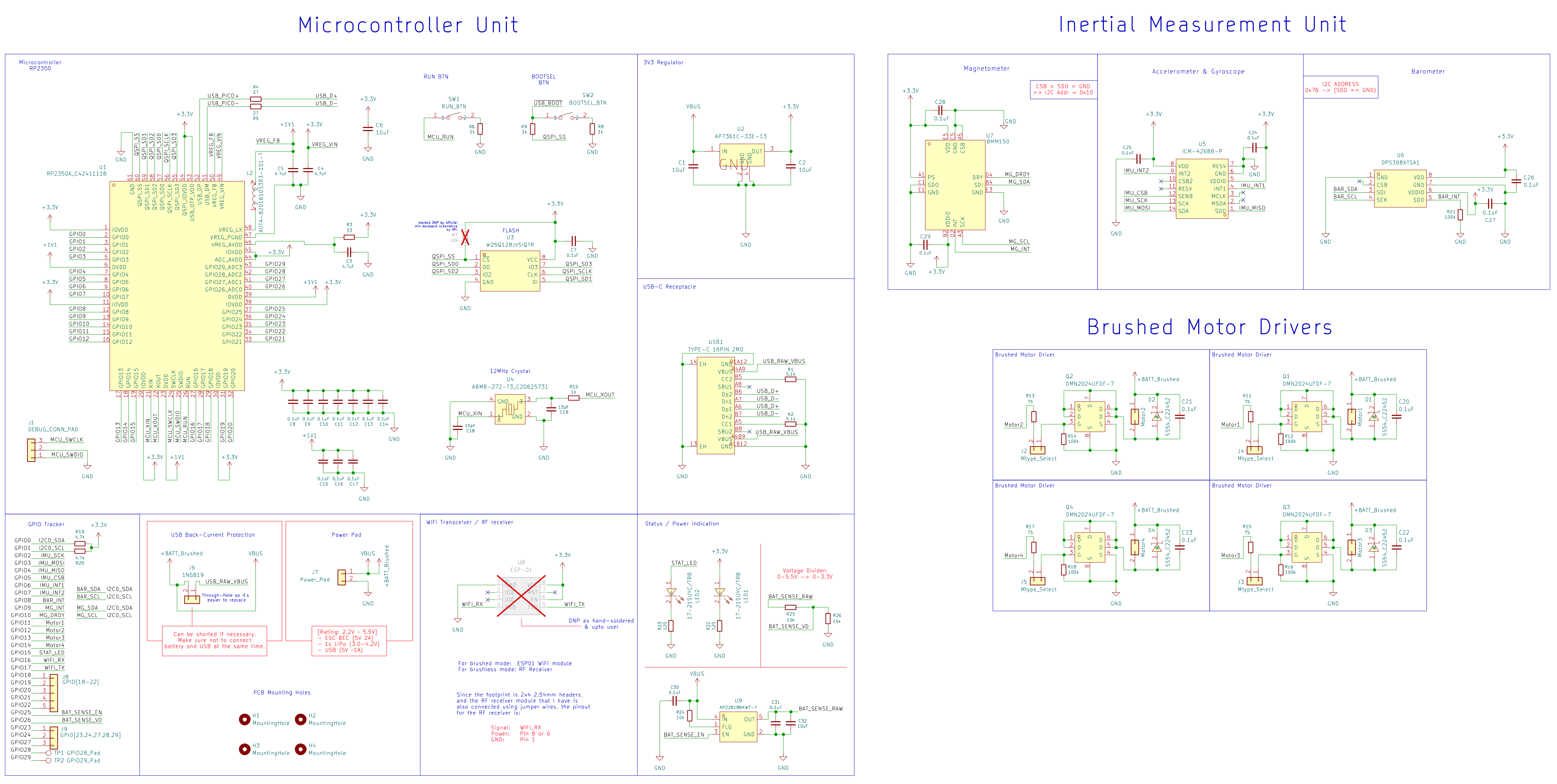
Note that the PCB and schematic files can be opened using KiCAD. They are located in the
/PCB/Quad0directory inside this repository.
Steps for viewing the PCB schematics and layout:
Quad0.kicad_pro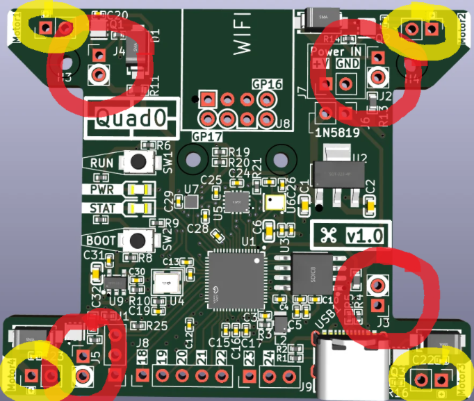
For Brushed: Short both pads together using solder or by soldering 2.54mm headers and adding jumper.
For Brushless: Un-short both pads if shorted, connect ESC signal pin to the pad marked with the thick white circle.
Each Mode selection connector is placed closest to the motor output it controls.
View /CAD directory for
.f3dand.stepfiles.
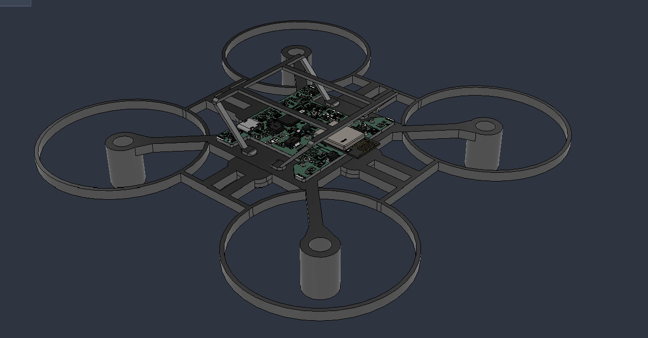
The frame for brushed version of the quadcopter was designed in Fusion360 and looks like this:
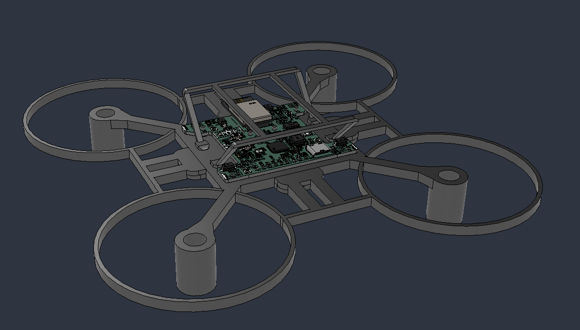
The frame is divided into 3 separate parts:
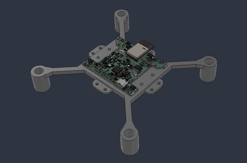
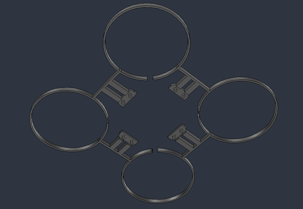
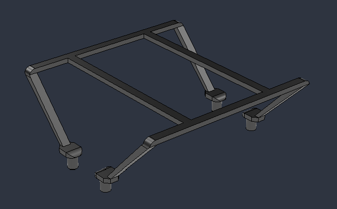
All the parts are made to friction-fit together using cylindrical extrusions and holes, the reason being to minimize the weight of the frame as using screws would add a LOT of weight. The friction fits would allow for either the cover or duct body to be omitted incase they are adding too much weight.
Please checkout the /Firmware directory to view the firmware source, current state and compiling / flashing instructions.
Note that the hardware is also fully supported by Betaflight. Instructions on how to setup betaflight will be provided after I physically test it myself to know what works.
Files required (gerber, bom, cpl) for ordering PCB Assembly from JLCPCB are available in PCB/Ordering/ directory.
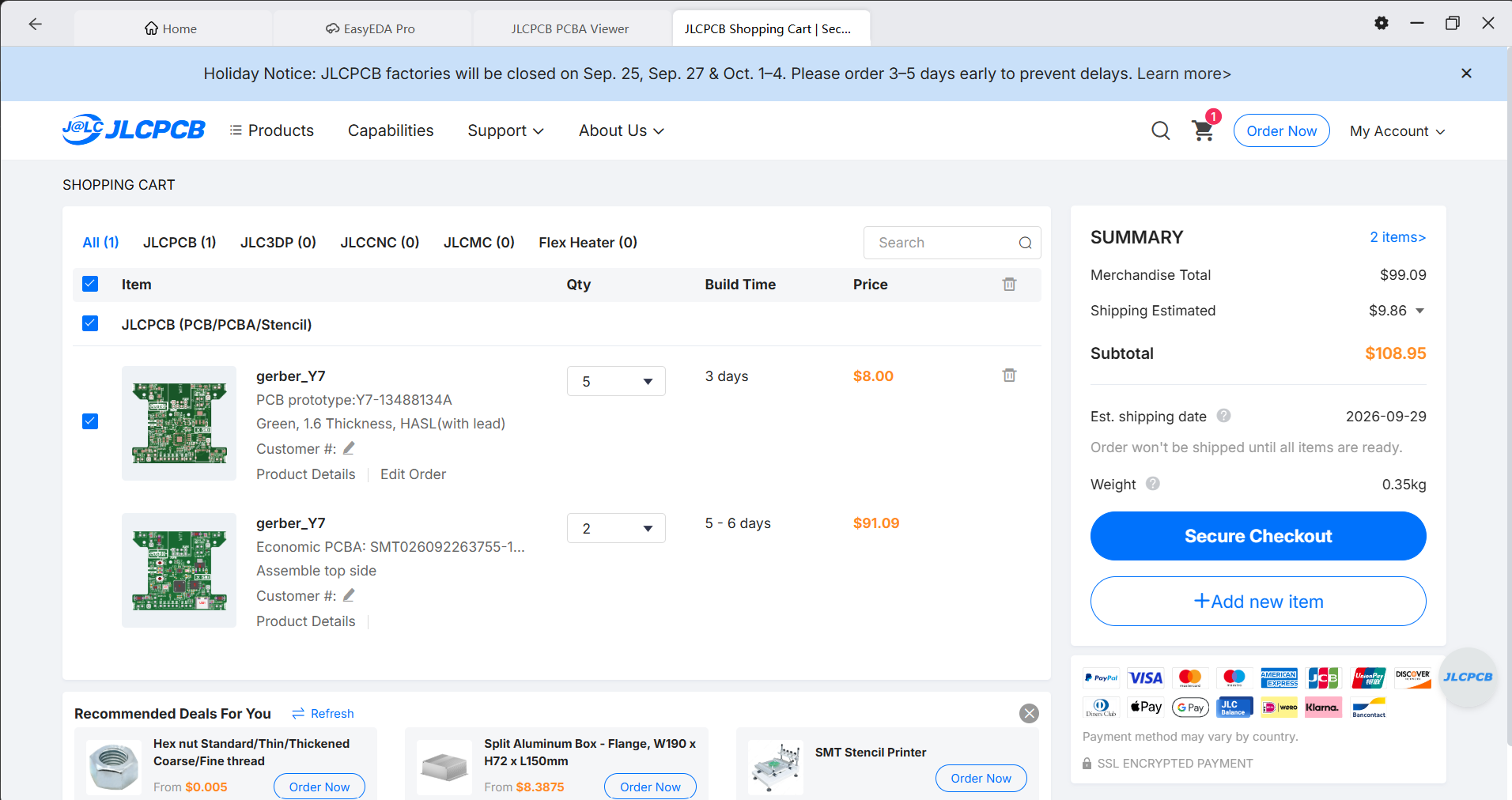
The grand total for this comes out to be at $108.95, including $9.86 for shipping. This cost can be brought down using coupon codes and also using JLCPCB'S desktop app: JLCONE.
This is after minimizing extended components usage and using basic PCBA (cheapest option). The PCB quantity and PCBA quantity is the MOQ (minimum order quantity): 5, 2 respectively.
Cart Screenshot:
Components required other than the ones that the PCBA covers are the following (for brushed mode):
This does not include shipping costs for components other than PCB+PCBA, since that will differ from place-to-place.
The project build is divided into 4 parts:
Please refer the Ordering Parts, PCBA section for this step.
Various components are required to be externally hand soldered onto the PCB. Focusing on the brushed mode, these are the components:
The following three .step files need to be 3d printed separately using a lightweight but sturdy material of your choice: (I will be testing it out myself, starting with PLA)
After that, It is recommended to test the quad with just the MainBody and then progressively add the DuctBody, Cover. This helps to ensure that the drone actually flies and is not held down by the weight of the frame.
The PCB sits on the cylindrical extrusions defined for it (as shown in the preview images). You can add tiny foam/similar rings between the PCB and the plastic body to dampen motor vibrations. Use adhesive tape (or whatever you prefer) to firmly hold the PCB in place with the main body, while also making sure you do not add extra unnecessary weight.
Please refer the /Firmware directory for this step.
That's it!
| Qty | Value | Footprint | References |
|---|---|---|---|
| 23 | 0.1uF | easyeda2kicad:C0402 | C10, C11, C12, C13, C14, C15, C16, C17, C20, C21, C22, C23, C24, C25, C26, C27 +7 |
| 5 | 100k | easyeda2kicad:R0402 | R12, R14, R16, R18, R21 |
| 4 | 10uF | easyeda2kicad:C0603 | C1, C2, C6, C32 |
| 4 | 1k | easyeda2kicad:R0402 | R6, R8, R9, R10 |
| 4 | 75 | easyeda2kicad:R0603 | R11, R13, R15, R17 |
| 4 | DMN2024UFDF-7 | easyeda2kicad:DFN2020MD-6_L2.0-W2.0-P0.65-BL | Q1, Q2, Q3, Q4 |
| 4 | MountingHole | MountingHole:MountingHole_2mm | H1, H2, H3, H4 |
| 4 | Mtype_Select | Connector_PinHeader_2.54mm:PinHeader_1x02_P2.54mm_Vertical | J2, J3, J4, J5 |
| 4 | SS54_C22452 | easyeda2kicad:SMA_L4.4-W2.8-LS5.4-R-RD | D1, D2, D3, D4 |
| 4 | motor | Connector_PinHeader_2.54mm:PinHeader_1x02_P2.54mm_Vertical | Motor1, Motor2, Motor3, Motor4 |
| 3 | 4.7uF | easyeda2kicad:C0402 | C3, C4, C5 |
| 2 | 10k | easyeda2kicad:R0402 | R24, R25 |
| 2 | 120 | easyeda2kicad:R0402 | R22, R23 |
| 2 | 15pF | easyeda2kicad:C0402 | C18, C19 |
| 2 | 17-21SUYC/TR8 | easyeda2kicad:LED0805-R-RD | LED1, LED2 |
| 2 | 27 | easyeda2kicad:R0402 | R4, R5 |
| 2 | 4.7k | easyeda2kicad:R0402 | R19, R20 |
| 2 | 5.1k | easyeda2kicad:R0402 | R1, R2 |
| 1 | 15k | easyeda2kicad:R0402 | R26 |
| 1 | 1N5819 | Connector_PinHeader_2.54mm:PinHeader_1x02_P2.54mm_Vertical | J6 |
| 1 | 33 | easyeda2kicad:R0402 | R3 |
| 1 | ABM8-272-T3_C20625731 | easyeda2kicad:CRYSTAL-SMD_4P-L3.2-W2.5-BL | U4 |
| 1 | AOTA-B201610S3R3-101-T | easyeda2kicad:IND-SMD_L2.0-W1.6_AOTA-B201610S3R3-101-T | L2 |
| 1 | AP22818BKWT-7 | easyeda2kicad:TSOT-23-5_L2.9-W1.6-P0.95-LS2.8-BL | U9 |
| 1 | AP7361C-33E-13 | easyeda2kicad:SOT-223_L6.5-W3.5-P2.30-LS7.0-BR | U2 |
| 1 | BMM150 | easyeda2kicad:WLCSP-12_L1.6-W1.6_BMM150 | U7 |
| 1 | BOOTSEL_BTN | easyeda2kicad:SW-SMD_L3.9-W3.0-P4.45 | SW2 |
| 1 | DEBUG_CONN_PAD | Connector_PinHeader_2.54mm:PinHeader_1x03_P2.54mm_Vertical | J1 |
| 1 | DPS368XTSA1 | easyeda2kicad:LGA-8_L2.5-W2.0-P0.65-TR_DPS368 | U6 |
| 1 | ESP-01 | easyeda2kicad:WIFIM-TH_8P-L24.7-W14.4-P2.54 | U8 |
| 1 | GPIO28_Pad | TestPoint:TestPoint_Pad_D1.0mm | TP1 |
| 1 | GPIO29_Pad | TestPoint:TestPoint_Pad_D1.0mm | TP2 |
| 1 | GPIO[18-22] | Connector_PinHeader_2.54mm:PinHeader_1x05_P2.54mm_Vertical | J8 |
| 1 | GPIO[23,24,27,28,29] | Connector_PinHeader_2.54mm:PinHeader_1x03_P2.54mm_Vertical | J9 |
| 1 | ICM-42688-P | easyeda2kicad:LGA-14_L3.0-W2.5-P0.50-BL | U5 |
| 1 | LOGO | LOGO | G*** |
| 1 | Power_Pad | Connector_PinHeader_2.54mm:PinHeader_1x02_P2.54mm_Vertical | J7 |
| 1 | RP2350A_C42411118 | easyeda2kicad:QFN-60_L7.0-W7.0-P0.40-TL-EP3.4 | U1 |
| 1 | RUN_BTN | easyeda2kicad:SW-SMD_L3.9-W3.0-P4.45 | SW1 |
| 1 | TYPE-C 16PIN 2MD | easyeda2kicad:USB-C-SMD_TYPE-C-16PIN-2MD-073 | USB1 |
| 1 | W25Q128JVSIQTR | easyeda2kicad:SOIC-8_L5.3-W5.3-P1.27-LS8.0-BL | U3 |
It measures 60 × 50 mm and has 4 copper layers, 1.6 mm thick.
100 parts, built around the RP2350A, ESP-01, BMM150 and DPS368XTSA1(TOKMAS). The full list of its parts is on this page, with links to each part's symbol and footprint where PCBKit's library has them.
From the Person-0/Quad0 repository on GitHub, at the commit this page was made from: the board is PCB/Quad0/Quad0.kicad_pcb and its schematic PCB/Quad0/Quad0.kicad_sch. PCBKit opens the board in the browser, with nothing to install.
Its repository states no licence, so its author keeps all rights: ask Person-0 before reusing the design.
SK-Electronics-Consulting/electronics-widgets
Small, Custom Tools for Electronics


ratmuds/spark
The PCB files for this project. The gerber and other PCBA files are in the production folder.

sequoia-hope/ultraroute
PCB autorouting experiments around copperroute: route jobs, leaderboards, board morphing

frindaddy/digichiver
Archival hardware/firmware for the MM54104 Digitalker chip

UC-Aerospace/Electrical-Tut-26
2026 Avionics tutorial example boards for UC Aerospace

andrewsharmon/rp2350-stepper-controller
Low-cost 10-axis sine-microstepping controller for small steppers on the RP2350 (PIO + DMA). WIP.
