2 layers90 × 100 mm
 shapoco/lcdtap85
A tool for mirroring or capturing I2C/SPI LCD displays
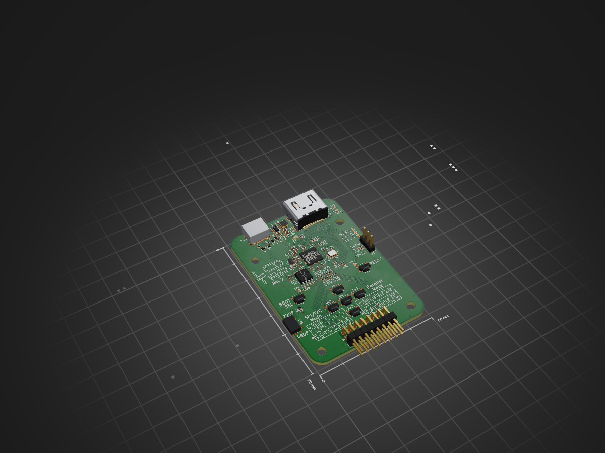
Lcdtap rp2350 is an open-source printed circuit board by shapoco, from the shapoco/lcdtap repository on GitHub. It is a 2-layer board of 50 × 70 mm with 100 parts on 91 nets, routed with 958 tracks and 275 vias.
It is built around the RP2350A, AP63203WU and W25Q32JVSSIQ, with the SKRPACE010, SESD5Z5V and MSK4010 among its other parts. Its parts include 31 resistors, 24 capacitors, 8 switches, 6 diodes and 4 connectors. It belongs with the lEDs and displays boards and the RP2350 boards of this library.



A library and its example design that receives LCD controller commands (via SPI or I2C) and outputs the framebuffer as a DVI-D signal.
See introduction page.
Supports multiple LCD controllers (ST7789, ILI9341, SSD1306, SSD1331, ST7032) and interfaces, selectable at runtime via an OSD menu.
Raspberry Pi Pico 2 W version with no video output: the captured screen is
read over WiFi through an HTTP JSON API and a built-in web UI
(http://lcdtap.local/). WiFi setup via the
Remote Setup page (WebSerial).
MIT License — see LICENSE.
| Qty | Value | Footprint | References |
|---|---|---|---|
| 14 | 100n | Capacitor_SMD:C_0402_1005Metric | C5, C6, C7, C8, C9, C10, C11, C12, C13, C14, C17, C19, C21, C24 |
| 14 | TestPoint_Small | TestPoint:TestPoint_Pad_D1.0mm | TP1, TP2, TP3, TP4, TP5, TP6, TP7, TP8, TP9, TP10, TP11, TP12, TP13, TP14 |
| 12 | 47 | Resistor_SMD:R_0402_1005Metric | R18, R19, R20, R21, R22, R23, R24, R25, R26, R27, R28, R29 |
| 8 | 270 | Resistor_SMD:R_0402_1005Metric | R7, R8, R9, R10, R11, R12, R13, R14 |
| 7 | SKRPACE010 | Button_Switch_SMD:SW_Push_1P1T_NO_Vertical_Wuerth_434133025816 | SW1, SW2, SW4, SW5, SW6, SW7, SW8 |
| 5 | 4.7u | Capacitor_SMD:C_0603_1608Metric | C1, C2, C15, C16, C18 |
| 4 | MountingHole | MountingHole:MountingHole_3.5mm | H1, H2, H3, H4 |
| 3 | SESD5Z5V | Diode_SMD:D_SOD-523 | D1, D2, D3 |
| 2 | 100 | Resistor_SMD:R_0402_1005Metric | R16, R17 |
| 2 | 15p | Capacitor_SMD:C_0402_1005Metric | C3, C4 |
| 2 | 1k | Resistor_SMD:R_0402_1005Metric | R1, R6 |
| 2 | 22u | Capacitor_SMD:C_0603_1608Metric | C22, C23 |
| 2 | 27 | Resistor_SMD:R_0402_1005Metric | R2, R3 |
| 2 | 5.1k | Resistor_SMD:R_0402_1005Metric | R4, R5 |
| 2 | LOGO | LOGO | G***, G*** |
| 2 | MSK4010 | Diode_SMD:D_SOD-523 | D5, D6 |
| 1 | 10k | Resistor_SMD:R_0402_1005Metric | R34 |
| 1 | 10u | Capacitor_SMD:C_0603_1608Metric | C20 |
| 1 | 33 | Resistor_SMD:R_0402_1005Metric | R33 |
| 1 | 4.7k | Resistor_SMD:R_0402_1005Metric | R15 |
| 1 | ABM8-272-T3 | Crystal:Crystal_SMD_3225-4Pin_3.2x2.5mm | Y1 |
| 1 | AOTA-B201610S3R3-101-T | shpc_discreet:AOTA-B201610S3R3-101-T | L1 |
| 1 | AP63203WU | Package_TO_SOT_SMD:TSOT-23-6 | U3 |
| 1 | Conn_01x03 | Connector_PinHeader_2.54mm:PinHeader_1x03_P2.54mm_Vertical | J3 |
| 1 | Conn_02x08_Odd_Even | shpc_mechanical:PinHeader_2x08_P2.54mm_Horizontal_Rev | J2 |
| 1 | HDMI-001S | shpc_mechanical:HDMI_A_Molex_208658-1001_Horizontal_Edge | J1 |
| 1 | KT-0603W | LED_SMD:LED_0603_1608Metric | D4 |
| 1 | LQH3NPZ4R7MMEL | shpc_discreet:LQH3NPZ4R7MMEL | L2 |
| 1 | RP2350A | Package_DFN_QFN:QFN-60-1EP_7x7mm_P0.4mm_EP3.4x3.4mm | U1 |
| 1 | SSSS811101 | shpc_mechanical:SW_SPDT_Alps_SSSS811101 | SW3 |
| 1 | SolderJumper_2_Open_Small | Jumper:SolderJumper-2_P1.3mm_Open_RoundedPad1.0x1.5mm | JP2 |
| 1 | TYPE-C16PIN | Connector_USB:USB_C_Receptacle_HCTL_HC-TYPE-C-16P-01A | P1 |
| 1 | W25Q32JVSSIQ | Package_SO:SOIC-8_5.3x5.3mm_P1.27mm | U2 |
It measures 50 × 70 mm and has 2 copper layers, 1.6 mm thick.
100 parts, built around the RP2350A, AP63203WU, W25Q32JVSSIQ and SKRPACE010. The full list of its parts is on this page, with links to each part's symbol and footprint where PCBKit's library has them.
From the shapoco/lcdtap repository on GitHub, at the commit this page was made from: the board is example/pico2_universal/kicad/lcdtap_rp2350.kicad_pcb and its schematic example/pico2_universal/kicad/lcdtap_rp2350.kicad_sch. PCBKit opens the board in the browser, with nothing to install.
Its repository states no licence, so its author keeps all rights: ask shapoco before reusing the design.


Galacs/esp32s3-poc-devboard
ESP32-S3 based PoC board made to test step-down power supply design, 24v level shifter, crystal circuits and RF circuit

openconcepts-ar/accel2d
This project aims to provide a graphics server system based on hardware accelerated graphics, and a easy way to develop the graphics primitives.


