| 15 | 100 | Resistor_SMD:R_0805_2012Metric_Pad1.20x1.40mm_HandSolder | R26, R27, R29, R30, R38, R41, R42, R43, R44, R45, R46, R47, R48, R49, R53 |
| 9 | 100nF | Capacitor_SMD:C_0805_2012Metric_Pad1.18x1.45mm_HandSolder | C1, C7, C9, C10, C11, C12, C18, C19, C20 |
| 7 | LED | Diode_SMD:D_0805_2012Metric_Pad1.15x1.40mm_HandSolder | D1, D4, D5, D9, D15, D16, D17 |
| 6 | 100K | Resistor_SMD:R_0805_2012Metric_Pad1.20x1.40mm_HandSolder | R15, R23, R25, R34, R35, R52 |
| 6 | 1k | Resistor_SMD:R_0805_2012Metric_Pad1.20x1.40mm_HandSolder | R6, R8, R9, R10, R11, R14 |
| 6 | 4K7 | Resistor_SMD:R_0805_2012Metric_Pad1.20x1.40mm_HandSolder | R16, R17, R18, R19, R50, R51 |
| 4 | 10K | Resistor_SMD:R_0805_2012Metric_Pad1.20x1.40mm_HandSolder | R7, R20, R21, R22 |
| 4 | 1K | Resistor_SMD:R_0805_2012Metric_Pad1.20x1.40mm_HandSolder | R28, R31, R32, R33 |
| 4 | 22pF | Capacitor_SMD:C_0805_2012Metric_Pad1.18x1.45mm_HandSolder | C2, C3, C13, C14 |
| 4 | AO3400A | Package_TO_SOT_SMD:SOT-23 | Q4, Q5, Q6, Q7 |
| 4 | MountingHole | MountingHole:MountingHole_3.2mm_M3 | H1, H2, H3, H4 |
| 4 | SS14 | Diode_SMD:D_SMA | D11, D12, D13, D14 |
| 4 | Screw_Terminal_01x02 | TerminalBlock_Phoenix:TerminalBlock_Phoenix_MKDS-1,5-2-5.08_1x02_P5.08mm_Horizontal | J10, J11, J12, J13 |
| 3 | 10k | Resistor_SMD:R_0805_2012Metric_Pad1.20x1.40mm_HandSolder | R1, R2, R12 |
| 2 | 0.1uF | Capacitor_SMD:C_0805_2012Metric_Pad1.18x1.45mm_HandSolder | C15, C16 |
| 2 | 1M | Resistor_SMD:R_0805_2012Metric_Pad1.20x1.40mm_HandSolder | R3, R13 |
| 2 | 1uF | Capacitor_SMD:C_0805_2012Metric_Pad1.18x1.45mm_HandSolder | C4, C5 |
| 2 | 22 | Resistor_SMD:R_0805_2012Metric_Pad1.20x1.40mm_HandSolder | R4, R5 |
| 2 | 47 | Resistor_SMD:R_0805_2012Metric_Pad1.20x1.40mm_HandSolder | R39, R40 |
| 2 | 47uF | Capacitor_THT:C_Radial_D5.0mm_H11.0mm_P2.00mm | C6, C8 |
| 2 | 680 | Resistor_SMD:R_0805_2012Metric_Pad1.20x1.40mm_HandSolder | R36, R37 |
| 2 | ABLS-16.000MHZ-D-4-T | Crystal:Crystal_SMD_HC49-SD_HandSoldering | Y1, Y2 |
| 2 | AVR-ISP-6 | Connector_PinHeader_2.54mm:PinHeader_2x03_P2.54mm_Vertical | J2, J4 |
| 2 | BLM21AG121BH1D | Inductor_SMD:L_0805_2012Metric_Pad1.05x1.20mm_HandSolder | FB1, FB2 |
| 2 | CG0603MLC-05E | Capacitor_SMD:C_0603_1608Metric_Pad1.08x0.95mm_HandSolder | RV1, RV2 |
| 2 | Jack-DC | Connector_BarrelJack:BarrelJack_CUI_PJ-102AH_Horizontal | J3, J8 |
| 2 | MF-MSMF050-2 | Fuse:Fuse_1812_4532Metric_Pad1.30x3.40mm_HandSolder | F1, F6 |
| 2 | MMSD4148T1G | Diode_SMD:D_SOD-123 | D2, D6 |
| 2 | TBU-CA-065-200-WH | Fuse:Fuse_Bourns_TBU-CA | F2, F3 |
| 2 | TP_5V | TestPoint:TestPoint_Pad_1.5x1.5mm | TP1, TP2 |
| 1 | 0805L200SLTHYR | Fuse:Fuse_0805_2012Metric_Pad1.15x1.40mm_HandSolder | F4 |
| 1 | 10nF | Capacitor_SMD:C_0805_2012Metric_Pad1.18x1.45mm_HandSolder | C21 |
| 1 | 10uF | Capacitor_SMD:C_0805_2012Metric_Pad1.18x1.45mm_HandSolder | C17 |
| 1 | 120 | Resistor_SMD:R_0805_2012Metric_Pad1.20x1.40mm_HandSolder | R24 |
| 1 | ATmega16U2-A | Package_QFP:TQFP-32_7x7mm_P0.8mm | U4 |
| 1 | ATmega328PB-A | Package_QFP:TQFP-32_7x7mm_P0.8mm | U6 |
| 1 | B5819W | Diode_SMD:D_SOD-123 | D3 |
| 1 | CDSOT23-SM712 | Package_TO_SOT_SMD:SOT-23 | D8 |
| 1 | Conn_01x04_Socket | Connector_JST:JST_PH_B4B-PH-K_1x04_P2.00mm_Vertical | J5 |
| 1 | Conn_02x05_Odd_Even | Connector_PinHeader_2.54mm:PinHeader_2x05_P2.54mm_Vertical | J9 |
| 1 | Conn_02x08_Odd_Even | Connector_PinHeader_2.54mm:PinHeader_2x08_P2.54mm_Vertical | J6 |
| 1 | DMG2305UX | Package_TO_SOT_SMD:SOT-23 | Q1 |
| 1 | FDN340P | Package_TO_SOT_SMD:SOT-23 | Q2 |
| 1 | LMV358 | Package_SO:SOIC-8_3.9x4.9mm_P1.27mm | U1 |
| 1 | LP2985-3.3 | Package_TO_SOT_SMD:SOT-23-5 | U3 |
| 1 | MAX485E | Package_SO:SOIC-8_3.9x4.9mm_P1.27mm | U7 |
| 1 | MCP23017_ML | Package_DFN_QFN:QFN-28-1EP_6x6mm_P0.65mm_EP4.25x4.25mm | U2 |
| 1 | NCP1117 | Package_TO_SOT_SMD:SOT-223-3_TabPin2 | U5 |
| 1 | PTSAHT120624V050 | Fuse:Fuse_1206_3216Metric_Pad1.42x1.75mm_HandSolder | F5 |
| 1 | SMAJ6.0A | Diode_SMD:D_SMA | D7 |
| 1 | SW_Push | Button_Switch_SMD:SW_Tactile_SPST_NO_Straight_CK_PTS636Sx25SMTRLFS | SW1 |
| 1 | Screw_Terminal_01x03 | TerminalBlock_Phoenix:TerminalBlock_Phoenix_MKDS-1,5-3-5.08_1x03_P5.08mm_Horizontal | J7 |
| 1 | TP10_5V | TestPoint:TestPoint_Pad_1.5x1.5mm | TP10 |
| 1 | TP5_5V | TestPoint:TestPoint_Pad_1.5x1.5mm | TP5 |
| 1 | TP8_5V | TestPoint:TestPoint_Pad_1.5x1.5mm | TP8 |
| 1 | TP9_GND | TestPoint:TestPoint_Pad_1.5x1.5mm | TP9 |
| 1 | TP_3.3V | TestPoint:TestPoint_Pad_1.5x1.5mm | TP6 |
| 1 | USB_B_Micro | Connector_USB:USB_Micro-B_Molex-105017-0001 | J1 |


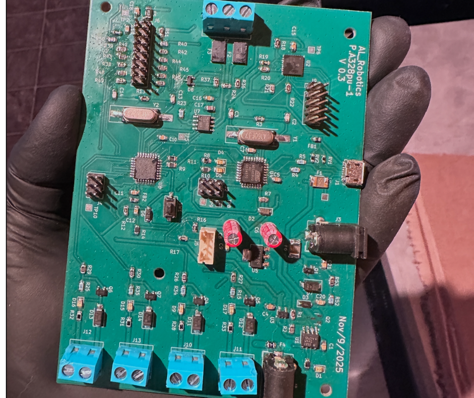
 .png)


