


4 layers96.1 × 65.8 mm
VariometerV2.2
oiver12/VariometerV2
Paragliding variometer: custom KiCad PCBs, ESP32 firmware, sensor fusion, e-ink UI, and desktop flight replay.
129 partsMIT
 oiver12/VariometerV2
Paragliding variometer: custom KiCad PCBs, ESP32 firmware, sensor fusion, e-ink UI, and desktop flight replay.
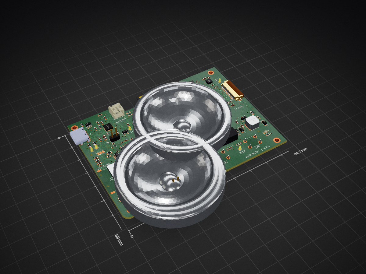
VariometerV2.2.1 is an open-source printed circuit board by oiver12, from the oiver12/VariometerV2 repository on GitHub, published under the MIT licence. It is a 4-layer board of 94.7 × 69.1 mm with 158 parts on 133 nets, routed with 1,307 tracks and 324 vias.
It is built around the ESP32-S3-WROOM-1-N8, DPS310 and QMC5883L, with the SRV05-4, BMI088 and TPS22916CNYFPR among its other parts. Its parts include 52 capacitors, 46 resistors, 12 ICs, 9 connectors and 7 diodes. It belongs with the sensors and measurement and lEDs and displays boards and the ESP32 boards of this library.


A paragliding variometer built from custom KiCad PCBs, ESP32 firmware, sensor fusion, and an e-ink flight interface.
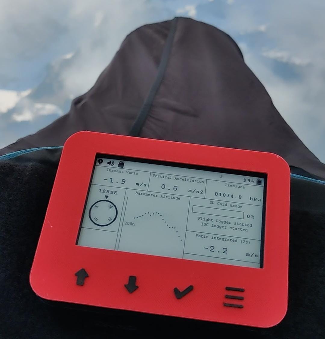
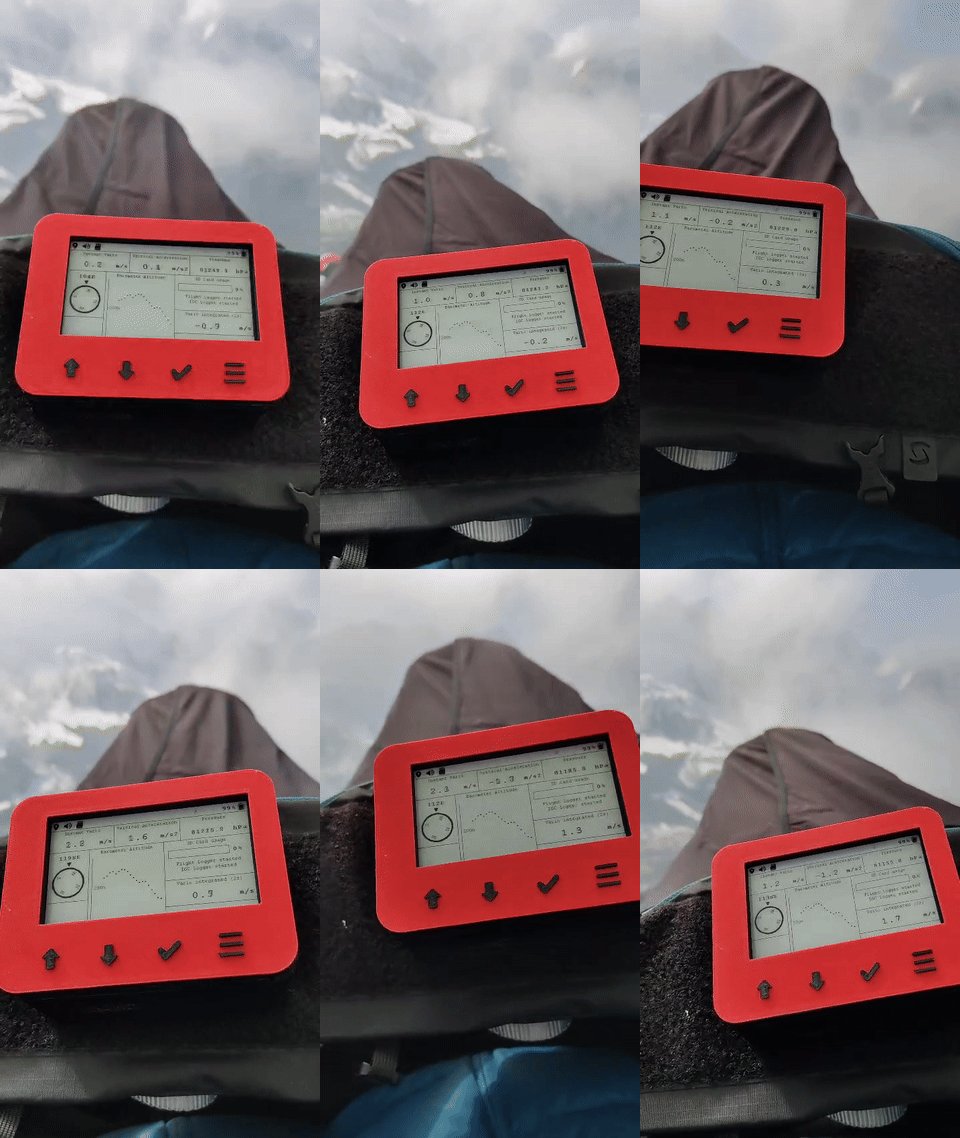
Flight-tested on my paragliding harness. Watch the flight video.
I started this project in 2021 as my Maturarbeit (Swiss high-school thesis), then continued developing it independently through 2024. I designed the custom PCBs and developed the firmware, sensor fusion pipeline, and e-ink rendering system, screens, and widgets. The enclosure/CAD work combines contributions from my brother and me.
| Front / top | Back / mirrored bottom |
|---|---|
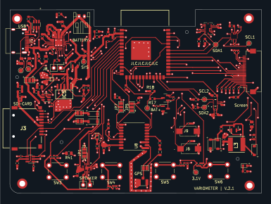 | 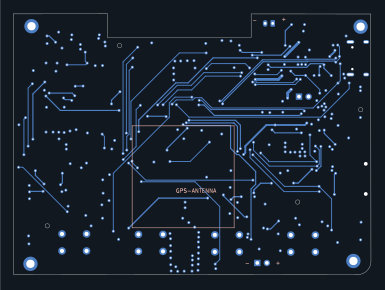 |
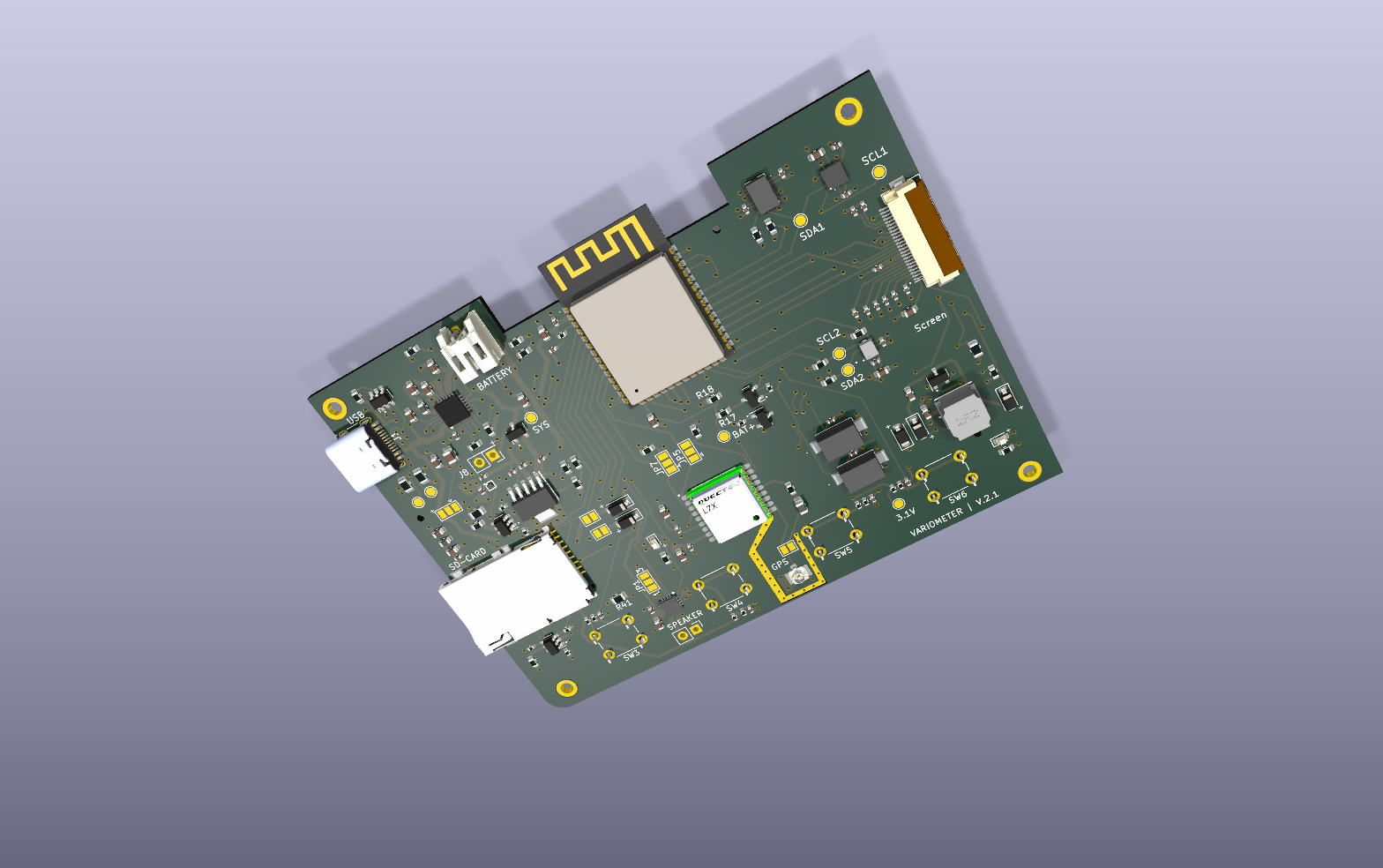
Schematic overview · Power · Sensors · Display · Peripherals
| Revision | Design files | PCB views | Schematic |
|---|---|---|---|
| 1.0 | Hardware/Version 1.0 | Top · bottom · 3D | SVG |
| 2.0 | Hardware/Version 2.0 | Top · bottom · 3D | SVG |
| 2.1 | Hardware/Version 2.1 | Top · bottom · 3D | SVG overview |
Case/ contains the enclosure designs and printing exports.
flowchart LR
    IMU["BMI088 IMU"] --> Drivers["Sensor drivers"]
    Baro["DPS310 barometer"] --> Drivers
    Mag["QMC5883L magnetometer"] --> Drivers
    Drivers --> Orientation["Quaternion orientation"]
    Orientation --> Acc["Vertical acceleration"]
    Drivers --> Kalman["Kalman altitude and climb rate"]
    Acc --> Kalman
    GPS["GPS / NMEA"] --> State["Flight state / device context"]
    Kalman --> State
    Airspace["Airspace parser"] --> State
    State --> UI["E-ink UI / screens / widgets"]
    State --> IGC["IGC logger"]
    State --> BLE["BLE module (experimental)"]
    State --> Sound["Sound"]
The sensor fusion pipeline runs across FreeRTOS tasks: the barometer task notifies the Kalman filter, while the acceleration task updates orientation and queues vertical acceleration. The filter combines these inputs into shared flight state, using queues, task notifications, and mutexes to coordinate the tasks.
Rendering and e-ink refresh run in separate tasks. GPS parsing, IGC logging, button input, battery management, sound, storage checks, and airspace parsing have their own task entry points.
| Directory | Purpose |
|---|---|
Hardware/, Case/ | PCB revisions and enclosure designs |
Software/variometer-software/ | ESP32 firmware |
Simulation/Main/ | FreeRTOS host runner and sensor mocks |
Screen_Simulator_Linux/, Screen_Simulator/ | Desktop UI simulators |
VariometerAnalysis/ | Sensor-log analysis and offline replay |
Sensor mocks replace hardware reads with recorded IMU, magnetometer, and pressure samples. A FreeRTOS simulation replays these recordings on a PC, allowing the firmware to run against recorded data.
The offline analysis tool runs the firmware’s quaternion and Kalman functions over the recorded sensor data:
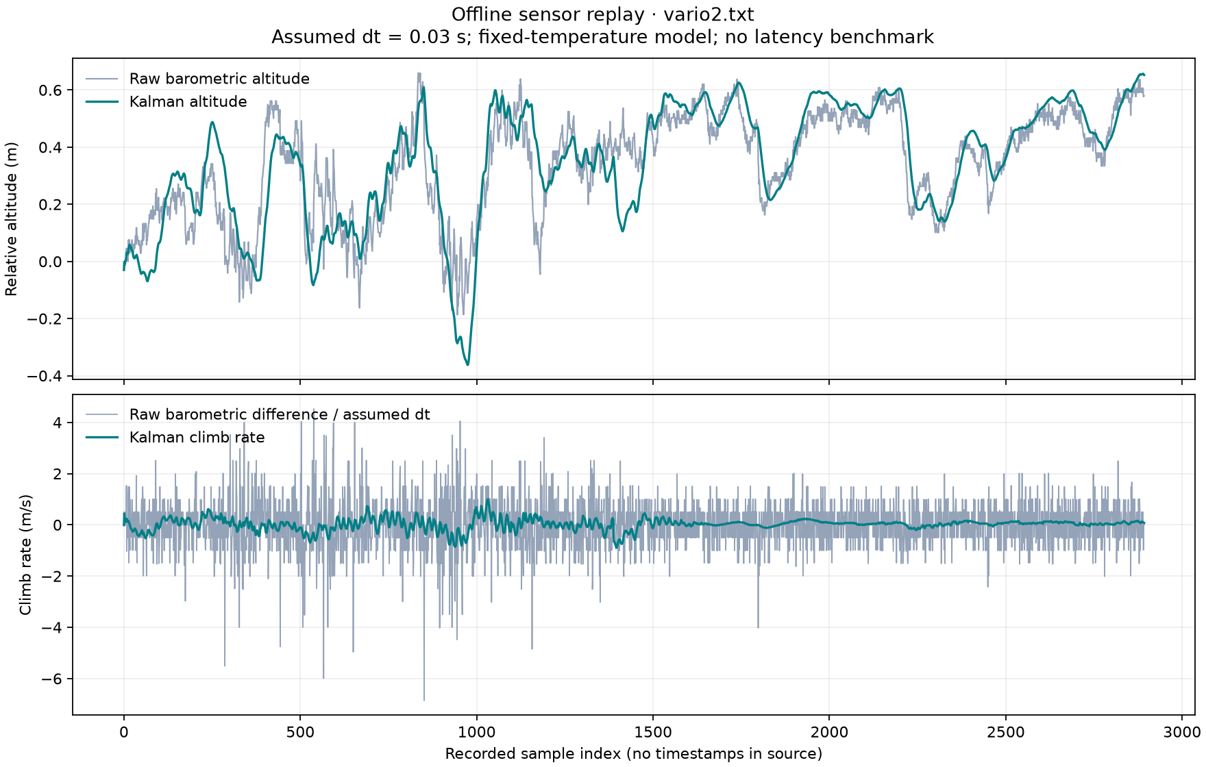
Barometric altitude and climb rate compared with the Kalman estimate. The recording has no timestamps, so replay uses an assumed sample interval; this plot is not a latency benchmark.
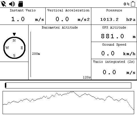
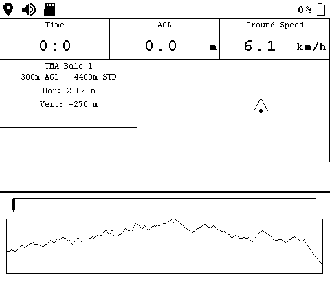
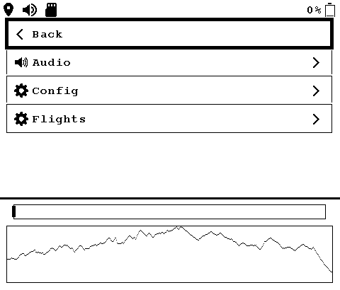
The Linux screen simulator exercises the custom UI independently of the device:
| Flight layout | Navigation layout | Settings |
|---|---|---|
 |  |  |
Replay and simulator instructions.
ESP32-S3 · ESP-IDF v5.1.4
See the developer guide for cloning, firmware build and flash commands, desktop simulation, and regenerating the visuals.
The project builds on FreeRTOS, Waveshare’s e-ink driver and GUI, STMicroelectronics bitmap fonts, Neil Kolban’s BLE library, Freescale/NXPMotionSense sensor fusion, kalman-clib, and other credited libraries. Full credits and license details are in THIRD_PARTY_NOTICES.txt.
My original software is licensed under MIT. Third-party code retains its own licenses, including the FIFO’s GPL-3.0-or-later obligations; the combined tree is not uniformly MIT-licensed. Enclosure/CAD contributions and third-party assets are outside this software license unless separately stated.
| Qty | Value | Footprint | References |
|---|---|---|---|
| 18 | 1uF | Capacitor_SMD:C_0402_1005Metric | C2, C11, C15, C16, C19, C23, C24, C25, C26, C27, C28, C29, C31, C32, C47, C48 +2 |
| 14 | 10k | Resistor_SMD:R_0603_1608Metric | R4, R7, R8, R15, R17, R25, R26, R35, R37, R38, R39, R40, R42, R43 |
| 13 | 100nF | Capacitor_SMD:C_0402_1005Metric | C3, C4, C5, C8, C17, C20, C35, C36, C37, C38, C39, C43, C50 |
| 11 | 10k | Resistor_SMD:R_0402_1005Metric | R1, R5, R20, R27, R28, R29, R30, R31, R44, R46, R48 |
| 8 | 10uF | Capacitor_SMD:C_0603_1608Metric | C7, C13, C14, C30, C42, C44, C45, C52 |
| 5 | 4.7uF | Capacitor_SMD:C_0603_1608Metric | C9, C33, C34, C40, C46 |
| 5 | B5819W SL | Diode_SMD:D_SOD-123 | D1, D3, D4, D5, D6 |
| 4 | 1k | Resistor_SMD:R_0402_1005Metric | R6, R45, R47, R49 |
| 4 | BTN1 | Button_Switch_THT:SW_PUSH_6mm_H4.3mm | SW3, SW4, SW5, SW6 |
| 4 | MountingHole_Pad | MountingHole:MountingHole_2.2mm_M2_DIN965_Pad | H1, H2, H3, H4 |
| 3 | SRV05-4 | Package_TO_SOT_SMD:SOT-23-6 | U1, U2, U3 |
| 2 | 1k | Resistor_SMD:R_0603_1608Metric | R9, R13 |
| 2 | 2.2uF | Capacitor_SMD:C_0603_1608Metric | C21, C22 |
| 2 | 5.1k | Resistor_SMD:R_0805_2012Metric | R2, R3 |
| 2 | AO3400A | Package_TO_SOT_SMD:SOT-23 | Q3, Q4 |
| 2 | AO3401A | Package_TO_SOT_SMD:SOT-23 | Q1, Q2 |
| 2 | JMP | Jumper:SolderJumper-2_P1.3mm_Open_Pad1.0x1.5mm | JP2, JP4 |
| 2 | SW | MainLibrary:PTS636SM25FSMTRLFS | J6, J9 |
| 2 | ~ | Jumper:SolderJumper-3_P1.3mm_Open_Pad1.0x1.5mm | JP5, JP7 |
| 1 | 0.47R | Resistor_SMD:R_0805_2012Metric | R34 |
| 1 | 1.5k | Resistor_SMD:R_0603_1608Metric | R24 |
| 1 | 100k | Resistor_SMD:R_0603_1608Metric | R36 |
| 1 | 10R | Resistor_SMD:R_0603_1608Metric | R10 |
| 1 | 10k B | Resistor_SMD:R_0805_2012Metric | R41 |
| 1 | 10k S | Resistor_SMD:R_0805_2012Metric | R32 |
| 1 | 10nF | Capacitor_SMD:C_0402_1005Metric | C18 |
| 1 | 15k | Resistor_SMD:R_0603_1608Metric | R18 |
| 1 | 1M | Resistor_SMD:R_0402_1005Metric | R19 |
| 1 | 1uF | Capacitor_SMD:C_0603_1608Metric | C51 |
| 1 | 1uH P | Inductor_SMD:L_0603_1608Metric | L1 |
| 1 | 20k | Resistor_SMD:R_0603_1608Metric | R22 |
| 1 | 22 | Resistor_SMD:R_0402_1005Metric | R33 |
| 1 | 220nF | Capacitor_SMD:C_0402_1005Metric | C41 |
| 1 | 22uF | Capacitor_SMD:C_0603_1608Metric | C1 |
| 1 | 270R | Resistor_SMD:R_0603_1608Metric | R16 |
| 1 | 3.1V TP | TestPoint:TestPoint_Pad_D1.5mm | TP2 |
| 1 | 47k | Resistor_SMD:R_0603_1608Metric | R21 |
| 1 | 47nF | Capacitor_SMD:C_0603_1608Metric | C12 |
| 1 | 47nH | Inductor_SMD:L_0805_2012Metric | L2 |
| 1 | 6.8uF | Capacitor_SMD:C_0805_2012Metric | C10 |
| 1 | 600 @ 100 MHz | Inductor_SMD:L_0603_1608Metric | FB1 |
| 1 | 9.1k | Resistor_SMD:R_0603_1608Metric | R23 |
| 1 | BLUE | LED_SMD:LED_0603_1608Metric | D7 |
| 1 | BMI088 | MainLibrary:BMI088 | U5 |
| 1 | BQ24196RGER | MainLibrary:QFN50P400X400X100-25N-D | IC3 |
| 1 | CC1 | TestPoint:TestPoint_Pad_D1.5mm | TP11 |
| 1 | CC2 | TestPoint:TestPoint_Pad_D1.5mm | TP12 |
| 1 | Conn_01x02 | Connector_JST:JST_PH_S2B-PH-K_1x02_P2.00mm_Horizontal | J7 |
| 1 | Conn_01x02 | Connector_PinHeader_2.54mm:PinHeader_1x02_P2.54mm_Vertical | J2 |
| 1 | Conn_01x24_MountingPin | Connector_FFC-FPC:Hirose_FH12-24S-0.5SH_1x24-1MP_P0.50mm_Horizontal | J10 |
| 1 | DPS310 | MainLibrary:DPS310XTSA1 | U4 |
| 1 | ESP32-S3-WROOM | MainLibrary:ESP32S3WROOM1 | IC1 |
| 1 | L76-L | MainLibrary:XCVR_L76-L | U8 |
| 1 | LED_CHRG | Connector_PinHeader_2.54mm:PinHeader_2x01_P2.54mm_Vertical | J8 |
| 1 | MAX98357A | MainLibrary:QFN50P300X300X80-17N | U7 |
| 1 | QMC5883L | MainLibrary:QMC5883L | U6 |
| 1 | RED | LED_SMD:LED_0603_1608Metric | D2 |
| 1 | SJ | Jumper:SolderJumper-2_P1.3mm_Open_Pad1.0x1.5mm | JP6 |
| 1 | SJMP | Jumper:SolderJumper-3_P1.3mm_Open_Pad1.0x1.5mm | JP8 |
| 1 | SRN6045TA-680M | MainLibrary:SRN6045TA | L3 |
| 1 | SolderJumper_3_Open | Jumper:SolderJumper-3_P1.3mm_Open_Pad1.0x1.5mm_NumberLabels | JP1 |
| 1 | TPS22916CNYFPR | MainLibrary:BGA4C40P2X2_78X78X50 | IC4 |
| 1 | TPS73701DCQR | MainLibrary:SOT127P706X180-6N | IC5 |
| 1 | TP_BATTERY | TestPoint:TestPoint_Pad_D1.5mm | TP1 |
| 1 | TP_SCL1 | TestPoint:TestPoint_Pad_D1.5mm | TP4 |
| 1 | TP_SCL2 | TestPoint:TestPoint_Pad_D1.5mm | TP6 |
| 1 | TP_SDA1 | TestPoint:TestPoint_Pad_D1.5mm | TP3 |
| 1 | TP_SDA2 | TestPoint:TestPoint_Pad_D1.5mm | TP5 |
| 1 | TP_SYS_LOAD | TestPoint:TestPoint_Pad_D1.5mm | TP10 |
| 1 | U.FL-R-SMT(01) | SamacSys_Parts:HRS_U.FL-R-SMT(01) | J5 |
| 1 | USB_C_Receptacle_USB2.0 | Connector_USB:USB_C_Receptacle_HRO_TYPE-C-31-M-12 | J1 |
| 1 | ~ | MainLibrary:TFP09212B | J3 |
oiver12/VariometerV2
Paragliding variometer: custom KiCad PCBs, ESP32 firmware, sensor fusion, e-ink UI, and desktop flight replay.

oiver12/VariometerV2
Paragliding variometer: custom KiCad PCBs, ESP32 firmware, sensor fusion, e-ink UI, and desktop flight replay.

oiver12/VariometerV2
Paragliding variometer: custom KiCad PCBs, ESP32 firmware, sensor fusion, e-ink UI, and desktop flight replay.

oiver12/VariometerV2
Paragliding variometer: custom KiCad PCBs, ESP32 firmware, sensor fusion, e-ink UI, and desktop flight replay.


sujaygouda123/foc-control
BLDC field-oriented-control board for a humanoid robot actuator. KiCad 10, Ø80 mm, 8 layers, 1.6 mm.


Yang-xy-svg/ESP_OpenMic
This project is subject to the licence in the LICENCE file, and even if that says it is an open source project, you cannot sell boards or cases bearing the Andrews & Arnold Ltd name, the A&A logo, the registered…

rjsc/BECom
BECom - Battery Emulator Companion - Open Source Hardware, designed to run dalathegreat/Battery-Emulator

Terrapin-Rocket-Team/SRAD-Avionics
Code and PCBs for the avionics subteam for the SRAD flight computer and side projects


It measures 94.7 × 69.1 mm and has 4 copper layers, 1.6 mm thick.
158 parts, built around the ESP32-S3-WROOM-1-N8, DPS310, QMC5883L and SRV05-4. The full list of its parts is on this page, with links to each part's symbol and footprint where PCBKit's library has them.
From the oiver12/VariometerV2 repository on GitHub, at the commit this page was made from: the board is Hardware/Version 2.1/VariometerV2.2.1/VariometerV2.2.1.kicad_pcb and its schematic Hardware/GPS_Test/L96-M33_Breakout/L96-M33_Breakout.kicad_sch. PCBKit opens the board in the browser, with nothing to install.
Its repository publishes it under the MIT licence: you may reuse it on that licence's terms (keep the author's notice, and for a copyleft licence share your changes alike).