2 layers47 × 28 mm
QSTExtended
-40℃~+85℃ 16bit 2.16V~3.6V 75uA Built-in temperature sensor I2C ±8Gs ±8Gs LGA-16(3x3) 3D Magnetic Sensors
The QMC5883L is a 3D Magnetic Sensor made by QST in a LGA-16(3x3) package with 16 pins. -40℃~+85℃ 16bit 2.16V~3.6V 75uA Built-in temperature sensor I2C ±8Gs ±8Gs LGA-16(3x3) 3D Magnetic Sensors.
PCBKit's library has its KiCad symbol (EasyEDA_Cloud:QMC5883L, from EasyEDA) and its footprint (EasyEDA_Cloud:LGA-16_L3.0-W3.0-P0.50-BL_SQ, from EasyEDA), ready for a KiCad board. JLCPCB lists it (part C976032). 34 open-source boards in 26 repositories on GitHub use it.
| Parameter | Conditions | As printed | Page |
|---|---|---|---|
| Supply Voltage | VDD; tested at 25°C | min 2.16 · max 3.6 V | 3 |
| I/O Voltage | VDDIO; tested at 25°C | min 1.65 · max 3.6 V | 3 |
| Standby Current | Total Current on VDD and VDDIO | typ 3 uA | 3 |
| Continuous Mode Current | Low Power Mode, OSR=64, ODR = 10Hz | typ 75 uA | 3 |
| Continuous Mode Current | High Power Mode, OSR=512, ODR = 10Hz | typ 100 uA | 3 |
| Continuous Mode Current | Low Power Mode, OSR=64, ODR = 50Hz | typ 150 uA | 3 |
| Continuous Mode Current | High Power Mode, OSR=512, ODR = 50Hz | typ 250 uA | 3 |
| Continuous Mode Current | Low Power Mode, OSR=64, ODR = 100Hz | typ 250 uA | 3 |
| Continuous Mode Current | High Power Mode, OSR=512, ODR = 100Hz | typ 450 uA | 3 |
| Continuous Mode Current | Low Power Mode, OSR=64, ODR = 200Hz | typ 450 uA | 3 |
| Continuous Mode Current | High Power Mode, OSR=512, ODR = 200Hz | typ 850 uA | 3 |
| Peak Current in Active State | Peak Current on VDD and VDDIO During Measurement | typ 2.6 mA | 3 |
| Sensor Field Range | Full Scale | min -8 · max 8 Gauss | 3 |
| Sensitivity | Field Range = ±2G; calibrated at zero field | typ 12000 LSB/G | 3 |
| Sensitivity | Field Range = ±8G; calibrated at zero field | typ 3000 LSB/G | 3 |
| Linearity (Best fit linear curve) | Field Range = ±2G | typ 0.1 %FS | 3 |
| Hysteresis | All Ranges | typ 0.3 %FS | 3 |
| Cross Axis Sensitivity | Cross field = 1 Gauss, Happlied = ±2 Gauss | typ 0.1 %/G | 3 |
| Temperature Sensor Sensitivity | Ta = -40℃~85℃ | typ 100 LSB/℃ | 3 |
| Digital Resolution | Change with Gain | min 0.1 · max 1 mGauss | 3 |
| Field Resolution | Standard deviation 100 Data, FS ±2G | typ 2 mGauss | 3 |
| Output Data Rate | Programmable. 10Hz/50Hz/100Hz/200Hz | min 10 · max 200 Samples/sec | 3 |
| Operating Temperature | min -40 · max 85 ℃ | 3 | |
| ESD | HB Model | min 2000 V | 3 |
| ESD | Charge Device Model | min 750 V | 3 |
| VDDIO | Tested at 25°C | min -0.3 · max 5.4 V | 4 |
| VDD | Tested at 25°C | min -0.3 · max 5.4 V | 4 |
| Storage Temperature | min -40 · max 125 ℃ | 4 | |
| Exposed to Magnetic Field (all directions) | Tested at 25°C | max 50000 Gauss | 4 |
| Voltage Input Low Level 1 VIL1 | SDA, SCL; max 0.3*VDDIO | min -0.3 V | 4 |
| POR Completion Time PORT | Time Period After VDD and VDDIO at Operating Voltage to Ready for I2C Commend and Analogy Measurement. | max 350 uS | 9 |
| Power off Voltage SDV | Voltage that Device Considers to be Power Down. | max 0.2 V | 9 |
| Power on Interval PINT | Time Period Required for Voltage Lower Than SDV to Enable Next POR | min 100 uS | 9 |


bassammorsy/stm32-flight-controller
Custom 4-layer STM32F405RGTx quadcopter flight controller PCB designed in KiCad. Betaflight compatible, 4S–6S LiPo input, SMT assembled by JLCPCB.

jh247247/DW1000-fan-video
Using UWB to make an indoor location system, to get a fan to point at me.
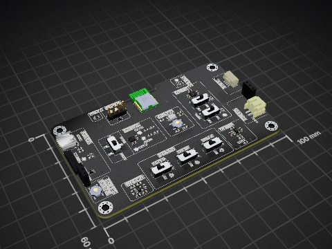


shubhamp2007/GPS-Travel-Navigator
A 5 inch offline maps with compass, powered by Radxa Cubie A7Z.

Yes. The symbol is EasyEDA_Cloud:QMC5883L and the footprint EasyEDA_Cloud:LGA-16_L3.0-W3.0-P0.50-BL_SQ, both drawn on this page. PCBKit places them on a board for you when you design with it.
LGA-16(3x3), with 16 pins. Its footprint is drawn on this page.
QST publishes it: the Datasheet link on this page opens it.
JLCPCB lists it as part C976032, with 0 in stock; the sellers' links on this page open their listings.
Parts like it in the library: the QMC5883P by QST. Check their datasheets: a part that fits the footprint may still differ in its ratings.
34 boards in 26 repositories on GitHub; the most starred are listed on this page, with their KiCad files.
