2 layers
Ledify
notaroomba/ledify
A super small addressable LED controller with USB-C PD up to 100W, a switchable 5V/12V output and Bluetooth!
12 parts1

 notaroomba/ledify1
A super small addressable LED controller with USB-C PD up to 100W, a switchable 5V/12V output and Bluetooth!
Ledify is an open-source printed circuit board by notaroomba, from the notaroomba/ledify repository on GitHub. It is a 4-layer board of 35.5 × 52.5 mm with 80 parts on 61 nets, routed with 528 tracks and 399 vias.
It is built around the ESP32-C6, AP63203WU and BMP581, with the FUSB302BMPX, LM61495QRPHRQ1 and OPT4001DNPRQ1 among its other parts. Its parts include 44 capacitors, 11 resistors, 10 ICs, 4 connectors and 4 inductors. It belongs with the ESP32 and RISC-V boards of this library.






Key Features • PCB • Firmware • Credits • License
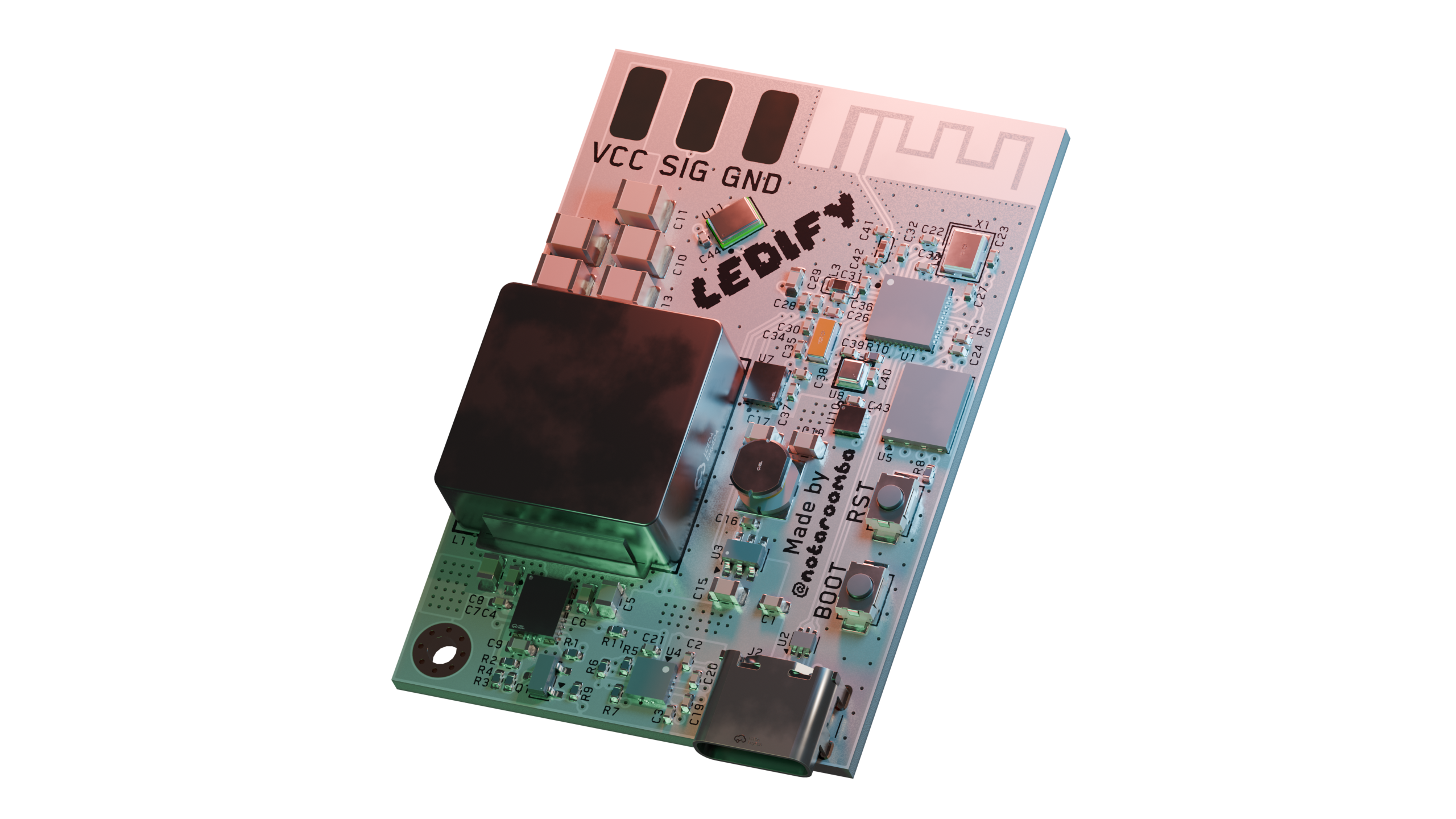
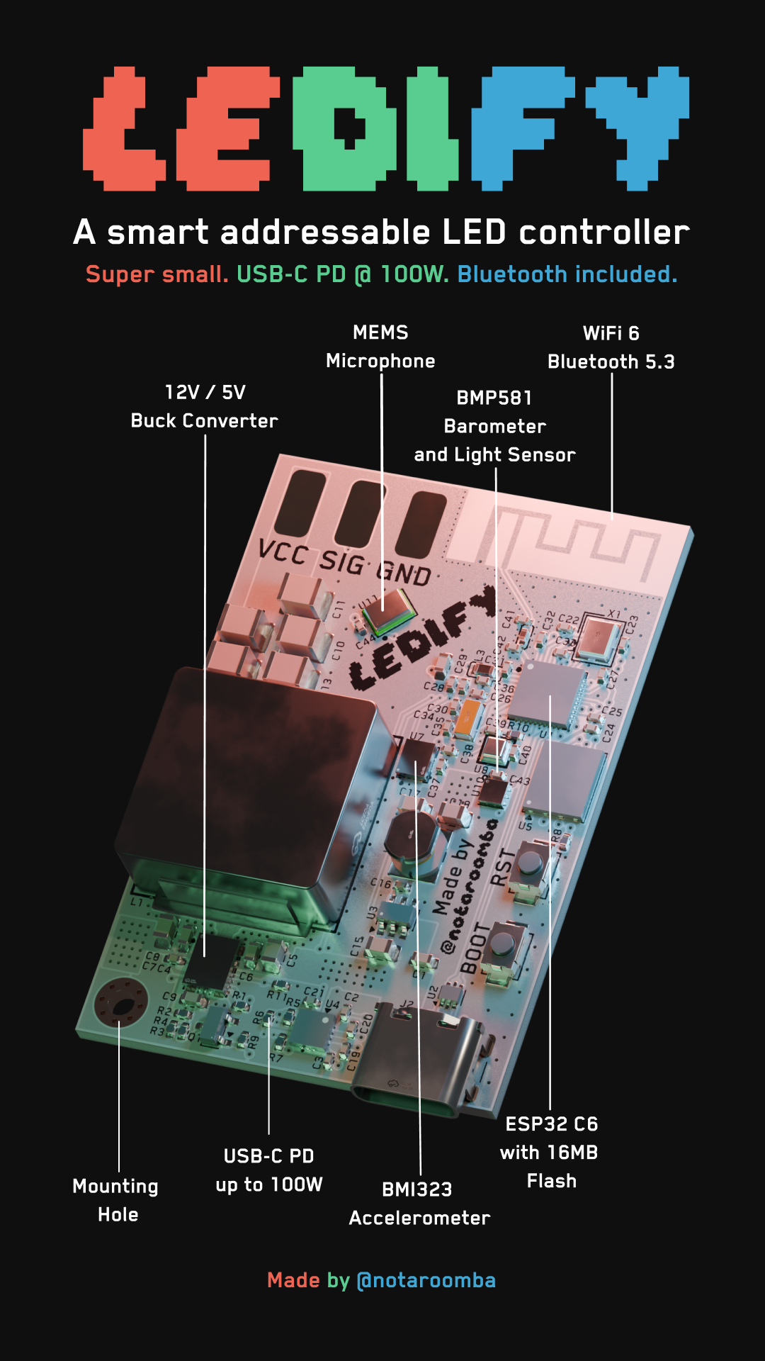
Designed in KiCad with attention to RF design and high current power delivery. The board is 4 layers with a solid ground plane under the ESP32, the flash and the antenna feed, and the LED buck follows the layout in the LM61495 datasheet.
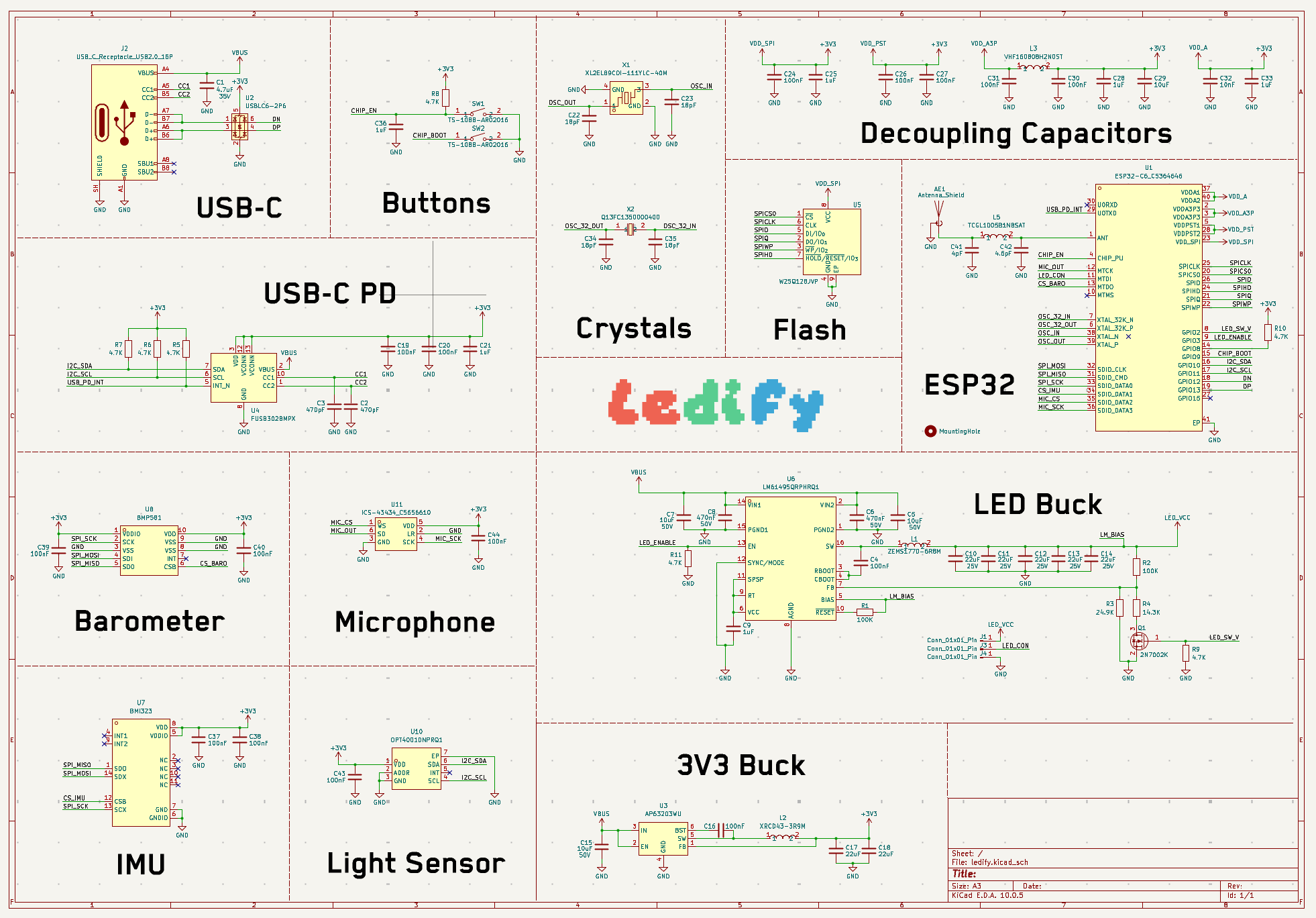
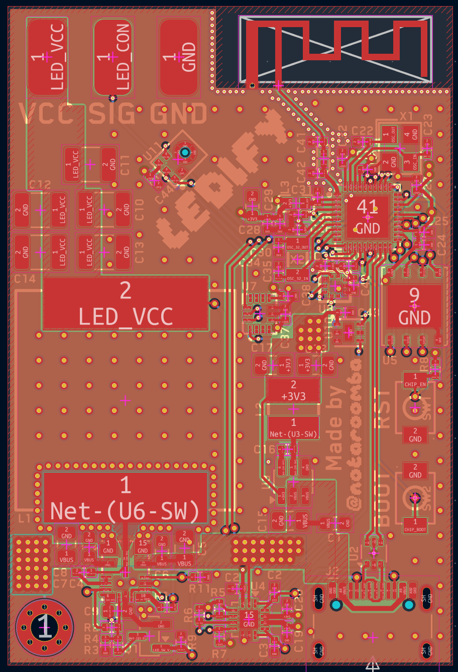
| GPIO | Net | Function |
|---|---|---|
| 2 | LED_SW_V | LED voltage select (low = 5V, high = 12V) |
| 3 | LED_ENABLE | LED buck enable |
| 5 | LED_CON | LED data (SIG pad) |
| 6 | MIC_OUT | Microphone I2S data |
| 22 | MIC_CS | Microphone I2S word select |
| 23 | MIC_SCK | Microphone I2S bit clock |
| 10 | I2C_SDA | I2C data (FUSB302B, OPT4001) |
| 11 | I2C_SCL | I2C clock (FUSB302B, OPT4001) |
| 16 | USB_PD_INT | FUSB302B interrupt |
| 18 | SPI_MISO | Sensor SPI |
| 19 | SPI_MOSI | Sensor SPI |
| 20 | SPI_SCK | Sensor SPI |
| 21 | CS_IMU | BMI323 chip select |
| 7 | CS_BARO | BMP581 chip select |
| 12 | DN | USB D- |
| 13 | DP | USB D+ |
| 9 | CHIP_BOOT | Boot button |
| 8 | - | Strapping pin, pulled up to 3V3 |
Rev 1 works; these are the changes queued for rev 2, each with the reason it is worth a spin of the board.
| Change | Why | How |
|---|---|---|
| Measure the strip current | The power limit and the warnings are arithmetic from the frame; a measurement catches strips that draw more than the model and lets the firmware show real watts | INA226 (I2C, address 0x40 next to the FUSB302 at 0x22 and the OPT4001) with a 2 mΩ 2512 shunt high side on the LED rail after the buck (10 A gives 20 mV, 1 mA resolution; 0.2 W in the shunt). Its VBUS pin reads the rail, so it also sees the 12 V setting. ALERT to GPIO14 for an over-current interrupt |
| Second data output | Two strips from one board, or a strip fed from both ends with the data going into each half | A second SIG pad on GPIO17 (a second RMT channel in firmware). Both outputs through a 74AHCT1G125 each: 3.3 V data into 5 V pixels is out of spec today and works only over short leads |
| 5.2 V setting for long strips | A one-end-fed 5 V strip sags towards the far end and goes warm; starting 0.2 V higher is what long-strip supplies do | 499 kΩ from U6 FB to the drain of a 2N7002, gate from GPIO0 with a 100 kΩ pull-down. In parallel with the 24.9 kΩ bottom resistor it makes 23.7 kΩ, so 1.0 V × (1 + 100/23.7) = 5.22 V on command; the 12 V setting (14.3 kΩ switched in by Q1) is untouched |
| Power injection pads | The real fix for the sag is a second feed into the far end, and it needs a 10 A home on the board | A second VCC/GND pad pair next to the first, both on the wide copper of the LED rail |
| A user button | The BOOT button already toggles the output in firmware, but it sits under the case and shares the strapping pin | A button on GPIO1 with its own pull-up, away from the strapping pins |
| Microphone port | Board 1's ICS-43434 passes the electrical checks but hears nothing: the acoustic port is suspected | Confirm the port hole in the copper and solder mask under the mic, and keep the mic away from the buck inductor |
Free GPIOs after rev 1: 0, 1, 14, 17 (4 and 15 are strapping pins). The feedback network today: 100 kΩ top, 24.9 kΩ bottom, 1.0 V reference, 5.02 V; Q1 adds 14.3 kΩ in parallel for 12.0 V.
The firmware in firmware/ is an ESP-IDF v6.1 project with drivers for everything on the board: USB-PD negotiation on the FUSB302B, the LED strip, the light sensor, IMU, barometer and microphone. It takes the same text commands from three places: the USB serial console, Bluetooth (it advertises as Ledify with the Nordic UART service, so nRF Connect or Bluefruit Connect work) and MQTT. Point it at a Wi-Fi network and a broker and it shows up in Home Assistant on its own as a light with eight effects (solid, rainbow, temperature, spectrum, meter, sound, VU, pulse), an auto-brightness switch, sliders for the pixel count and the sound, light and temperature tunables, a chip-type select and illuminance, temperature, pressure and sound sensors. The colour source, brightness source and overlay can also be mixed freely, so a rainbow VU meter that dims in a dark room is three commands. Brightness is capped automatically to what the USB-PD contract can supply, so a long strip on a laptop port dims instead of browning out.
| Command | Action |
|---|---|
on / off | LED buck on or off |
rgb R G B | Fills the strip with a color (0-255 each) |
level N | Brightness cap (0-255) |
count N | How many pixels to drive (up to 1000, also a slider in Home Assistant) |
type ws2812 | Chip type: ws2812 (B/C/D/E, WS2813, WS2815), ws2811, sk6812, sk6812w, ws2816 |
mode NAME | Preset, also the Home Assistant effect: solid, rainbow, temp (blue-white-red from the temperature), spectrum (bass/mid/treble bars), meter, sound, vu, pulse |
color / bright / overlay | Mix your own: colour source, brightness source (level or sound), overlay (none, vu, pulse) |
auto on / auto off | Brightness follows the ambient light sensor, off below a night threshold |
gain N, lux LO HI, night N, temp LO HI | Saved tunables for the sound, light and temperature styles; temp 21.5 feeds a temperature in |
volt 5 / volt 12 | Selects the output voltage, turns the output off first. 12V needs a 15V+ PD contract |
status | JSON with the PD contract, network state, lux, temperature, pressure, motion and sound level |
pd / net | The charger's offered voltages / Wi-Fi and MQTT state |
wifi SSID PASS | Saves the Wi-Fi credentials and restarts |
mqtt URL USER PASS | Saves the broker and restarts |
ota URL | Updates the firmware over Wi-Fi, with automatic rollback |
The output always boots at 5V and off, and the board asks the charger for the highest voltage up to 20V as soon as it starts. Credentials, the strip length, the chip type and the tunables are stored in the ESP32's NVS partition, never in the code. SIG is 3.3V logic going to the strip's DIN; the wiring notes, MQTT topics and the Mosquitto-on-Railway broker setup are in firmware/README.md.
cd firmware
source ~/.espressif/tools/activate_idf_v6.1.sh
idf.py build
idf.py -p /dev/cu.usbmodem2101 flash monitorThis project uses:
MIT
notaroomba.dev · GitHub @NotARoomba ·
| Qty | Value | Footprint | References |
|---|---|---|---|
| 14 | 100nF | Capacitor_SMD:C_0402_1005Metric | C16, C19, C20, C24, C26, C27, C30, C31, C37, C38, C39, C40, C43, C44 |
| 7 | 4.7K | Resistor_SMD:R_0402_1005Metric | R5, R6, R7, R8, R9, R10, R11 |
| 5 | 1uF | Capacitor_SMD:C_0402_1005Metric | C21, C25, C28, C33, C36 |
| 5 | 22uF 25V | Capacitor_SMD:C_1210_3225Metric | C10, C11, C12, C13, C14 |
| 4 | 18pF | Capacitor_SMD:C_0402_1005Metric | C22, C23, C34, C35 |
| 3 | 10uF 50V | Capacitor_SMD:C_0805_2012Metric | C5, C7, C15 |
| 3 | Conn_01x01_Pin | Connector_Wire:SolderWirePad_1x01_SMD_3x6mm | J1, J3, J4 |
| 2 | 100K | Resistor_SMD:R_0402_1005Metric | R1, R2 |
| 2 | 22uF | Capacitor_SMD:C_0805_2012Metric | C17, C18 |
| 2 | 470nF 50V | Capacitor_SMD:C_0603_1608Metric | C6, C8 |
| 2 | 470pF | Capacitor_SMD:C_0402_1005Metric | C2, C3 |
| 2 | TS-1088-AR02016 | lcsc:SW-SMD_L3.9-W3.0-P4.45 | SW1, SW2 |
| 1 | 100nF | Capacitor_SMD:C_0402_1005Metric_Pad0.74x0.62mm_HandSolder | C4 |
| 1 | 10nF | Capacitor_SMD:C_0402_1005Metric | C32 |
| 1 | 10uF | Capacitor_SMD:C_0603_1608Metric | C29 |
| 1 | 14.3K | Resistor_SMD:R_0402_1005Metric | R4 |
| 1 | 1uF | Capacitor_SMD:C_0603_1608Metric | C9 |
| 1 | 24.9K | Resistor_SMD:R_0402_1005Metric | R3 |
| 1 | 2N7002K | Package_TO_SOT_SMD:SOT-23 | Q1 |
| 1 | 4.6pF | Capacitor_SMD:C_0402_1005Metric | C42 |
| 1 | 4.7uF 35V | Capacitor_SMD:C_0603_1608Metric | C1 |
| 1 | 4pF | Capacitor_SMD:C_0402_1005Metric | C41 |
| 1 | AP63203WU | Package_TO_SOT_SMD:TSOT-23-6 | U3 |
| 1 | Antenna_Shield | RF_Antenna:Texas_SWRA117D_2.4GHz_Right | AE1 |
| 1 | BMI323 | lcsc:LGA-14_L3.0-W2.5-P0.50-TL_QMI8658A | U7 |
| 1 | BMP581 | lcsc:LGA-10_L2.0-W2.0-P0.50-TL_BMP581 | U8 |
| 1 | ESP32-C6_C5364646 | lcsc:QFN-40_L5.0-W5.0-P0.40-TL-EP3.3 | U1 |
| 1 | FUSB302BMPX | Package_DFN_QFN:WQFN-14-1EP_2.5x2.5mm_P0.5mm_EP1.45x1.45mm | U4 |
| 1 | ICS-43434_C5656610 | lcsc:MIC-SMD_6P-L3.5-W2.7-P0.90-BL | U11 |
| 1 | LM61495QRPHRQ1 | lcsc:VQFN-16_L4.5-W3.5-P0.50-TL_TI_RPH | U6 |
| 1 | MountingHole | MountingHole:MountingHole_2.2mm_M2_Pad_Via | H1 |
| 1 | OPT4001DNPRQ1 | lcsc:USON-6_L2.0-W2.0-P0.65-BL-EP | U10 |
| 1 | Q13FC1350000400 | lcsc:FC-135R_L3.2-W1.5 | X2 |
| 1 | TCGL1005B1N8SAT | lcsc:L0402 | L5 |
| 1 | USBLC6-2P6 | Package_TO_SOT_SMD:SOT-666 | U2 |
| 1 | USB_C_Receptacle_USB2.0_16P | Connector_USB:USB_C_Receptacle_HCTL_HC-TYPE-C-16P-01A | J2 |
| 1 | VHF160808H2N0ST | lcsc:L0603 | L3 |
| 1 | W25Q128JVP | Package_SON:WSON-8-1EP_6x5mm_P1.27mm_EP3.4x4.3mm | U5 |
| 1 | XL2EL89COI-111YLC-40M | lcsc:CRYSTAL-SMD_4P-L3.2-W2.5-BL | X1 |
| 1 | XRCD43-3R9M | lcsc:IND-SMD_L4.0-W3.2_XRCD43 | L2 |
| 1 | ZEMS1770-6R8M | lcsc:IND-SMD_L17.5-W17.5_SLO1770H | L1 |
It measures 35.5 × 52.5 mm and has 4 copper layers, 1.58 mm thick.
80 parts, built around the ESP32-C6, AP63203WU, BMP581 and FUSB302BMPX. The full list of its parts is on this page, with links to each part's symbol and footprint where PCBKit's library has them.
From the notaroomba/ledify repository on GitHub, at the commit this page was made from: the board is pcb/ledify.kicad_pcb and its schematic pcb/_restore_backup_2026-09-29T14-25-15-173/ledify.kicad_sch. PCBKit opens the board in the browser, with nothing to install.
Its repository states no licence, so its author keeps all rights: ask notaroomba before reusing the design.
notaroomba/ledify
A super small addressable LED controller with USB-C PD up to 100W, a switchable 5V/12V output and Bluetooth!

l3wi/IWR-AOP-MODULE
60 GHz mmWave radar module built around TI's IWR6843AOP: USB-C or carrier-socket operation. KiCad 10, JLCPCB-ready.

LordsBoards/OPT4001-STEMMA-QT-Light-Sensor
A STEMMA QT board using the Texas Instrument's OPT4001 ambient light sensor

electgpl/NodeAlarm
This project is a simple motion sensor with subgigahertz FSK interface based on RFM69 and ESP32C3 RISC-V core, all devices are woken from deep sleep by the IRQ of AS312 PIR sensor, this project is open source and…

waxters-osu/senior_design_low_noise_visibility_drone
Low-noise & low-visibility drone senior design project.

awetzelkern/CASE
Miminal flight computer designed to be a stepping-stone into creating PCB hardware and software for a fully custom thrust-vectored rocket.


Mig-M27/Avionics-PCBs
Este repositório é usado para gerir as versões dos projetos KiCAD do sistema de Avionics da Porto Space Team. Está dividido em 2 secções: 1.

mikelawrence/esphome-indoor-multi-sensor-hardware
ESPHome Indoor Multi-Sensor hardware. This design supports Radar/PIR Presence, Temperature, Humidity, Pressure, Light, CO2, CO, VOC, NOX and PM sensors.