
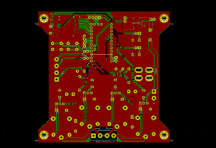
2 layers290.1 × 130 mm

 motivemachine/dual_swing_gate_controller7
A relay-driven dual DC motor controller for a double-swing gate opener. Uses Arduino and LoRa. This repo is a mirror for:
DrivewayGateControl is an open-source printed circuit board by motivemachine, from the motivemachine/dual_swing_gate_controller repository on GitHub, published under the MIT licence. It is a 2-layer board of 99.7 × 99.1 mm with 56 parts on 51 nets, routed with 325 tracks and 28 vias.
It is built around the AMS1117-3.3. Its parts include 10 resistors, 8 capacitors, 8 diodes, 6 connectors and 6 switches. It belongs with the robots and motor control and radio and wireless boards and the AVR (ATmega, ATtiny) boards of this library.
Having built a custom driveway gate and hinge setup I found myself shocked at what a quality dual-swing gate opener costs these days. More importantly, they have rather a lack of customization available in how you control or communicate with them, so I've set out to build my own with a pair of 12v linear actuators and a Semtech SX1287 LORA radio module. This is a work in progress.
I'll be building a custom PCB for the whole thing, but I've tried to design this in such a way that any number of Arduino and related modules would work if hand-wired with jumpers, perfboard, breadboard, etc. Most parts are through-hole, and the ones that are surface mount are large enough hand soldering should be easy. Also makes for easy customization.
Schematic and first soldered board is complete. Code testing has begun, and has been mostly reliable with a few adjustments needed in error handling functions and long-term robust-ness.
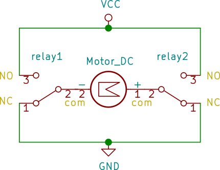
Shown here is the relay configuration in a simple H-Bridge. By switching seperate relays, any leg can be made positive, while the other remains grounded, causing the DC motor to be able to turn in two directions. This is very fault tolerant too- if any relay became stuck or failed, the motor would have either both leads grounded, or both leads at 12 volts, neither one of which would allow current to flow, therefore the motor will remain stopped. If the linear actuator is moving, it will of course stop when it reaches the built-in limit switches.
Avid home DIY'ers might recognize this as similar to wiring a 3-way light switch, but backwards. The other difference is that AC power has no single direction of current flow, nor does a lightbulb care which way the current flows.
Added support for the TOPENS HLR01 Homelink-compatible receiver using a single-button toggle on pin A0.
Wiring:
Pressing the assigned Homelink button in your vehicle will toggle the gate state (open ↔ close). Includes debounce and LED2 visual feedback. No PCB rework needed — uses the existing A0 breakout header.
Note: Magnetometer code is commented out in v2.0 but can be easily re-enabled.
| Qty | Value | Footprint | References |
|---|---|---|---|
| 6 | 1n4001 | Diode_THT:D_A-405_P7.62mm_Horizontal | D3, D4, D5, D6, D7, D9 |
| 4 | 0.1uf | Capacitor_THT:C_Disc_D4.7mm_W2.5mm_P5.00mm | C3, C4, C6, C8 |
| 4 | 1k | Resistor_THT:R_Axial_DIN0207_L6.3mm_D2.5mm_P7.62mm_Horizontal | R5, R6, R8, R9 |
| 4 | 2N3904 | Package_TO_SOT_THT:TO-92_Inline_Wide | Q1, Q2, Q3, Q4 |
| 4 | MountingHole_Pad | MountingHole:MountingHole_3.2mm_M3_Pad_Via | H1, H2, H3, H4 |
| 2 | 0.1 | Resistor_THT:R_Axial_DIN0207_L6.3mm_D2.5mm_P10.16mm_Horizontal | R7, R10 |
| 2 | 3k3 | Resistor_THT:R_Axial_DIN0207_L6.3mm_D2.5mm_P7.62mm_Horizontal | R3, R4 |
| 2 | 470uf | Capacitor_THT:CP_Radial_D12.5mm_P5.00mm | C5, C7 |
| 2 | Fuse | Fuse:Fuse_Blade_Mini_directSolder | F1, F2 |
| 2 | INA219BIDCNR | Package_TO_SOT_SMD:SOT-23-8 | U4, U5 |
| 2 | LED | LED_THT:LED_D5.0mm | D1, D2 |
| 2 | R | Resistor_THT:R_Axial_DIN0207_L6.3mm_D2.5mm_P7.62mm_Horizontal | R1, R2 |
| 1 | 100uf | Capacitor_THT:CP_Radial_D7.5mm_P2.50mm | C9 |
| 1 | 22uf | Capacitor_THT:CP_Radial_D5.0mm_P2.50mm | C1 |
| 1 | AMS1117-3.3 | Package_TO_SOT_SMD:SOT-223-3_TabPin2 | U1 |
| 1 | ArduinoProMini_a | MainWorking:ArduinoProMini_a | U2 |
| 1 | D | Diode_THT:D_A-405_P7.62mm_Horizontal | 1n4001 |
| 1 | LOGO | MainWorking:cateyes_small_ears | G*** |
| 1 | LOGO_MWM_med | MainWorking:LOGO_MWM_med | G*** |
| 1 | LoRa_Ra-02 | MainWorking:LORA_SX1278_Module | U3 |
| 1 | Motor_Connects | TerminalBlock:TerminalBlock_bornier-4_P5.08mm | J4 |
| 1 | close | Button_Switch_THT:SW_PUSH_6mm_H8.5mm | SW1 |
| 1 | gpio1 | Connector_PinHeader_2.54mm:PinHeader_1x04_P2.54mm_Vertical | J5 |
| 1 | gpio2 | Connector_PinHeader_2.54mm:PinHeader_1x04_P2.54mm_Vertical | J6 |
| 1 | magnetometer | TerminalBlock:TerminalBlock_bornier-4_P5.08mm | J2 |
| 1 | open | Button_Switch_THT:SW_PUSH_6mm_H8.5mm | SW2 |
| 1 | power | TerminalBlock:TerminalBlock_bornier-2_P5.08mm | J3 |
| 1 | relay1 | Relay_THT:Relay_SPDT_SANYOU_SRD_Series_Form_C | K1 |
| 1 | relay2 | Relay_THT:Relay_SPDT_SANYOU_SRD_Series_Form_C | K2 |
| 1 | relay3 | Relay_THT:Relay_SPDT_SANYOU_SRD_Series_Form_C | K3 |
| 1 | relay4 | Relay_THT:Relay_SPDT_SANYOU_SRD_Series_Form_C | K4 |
| 1 | serial_header | Connector_PinHeader_2.54mm:PinHeader_1x02_P2.54mm_Vertical | J1 |

pascallanger/DIY-Multiprotocol-TX-Module
Multiprotocol TX Module (or MULTI-Module) is a 2.4GHz transmitter module which controls many different receivers and models.

fossasia/pslab-hardware
PSLab Hardware Design and Schematics https://pslab.io


MaltWhiskey/Mega-Cube
16x16x16 PL9823 Cube with Teensy 4.0 and FlexIO driver


shamansystems/Cheap-FOCer-2
Low-Cost Motor Controller based on the VESC 6
It measures 99.7 × 99.1 mm and has 2 copper layers, 1.6 mm thick.
56 parts, built around the AMS1117-3.3. The full list of its parts is on this page, with links to each part's symbol and footprint where PCBKit's library has them.
From the motivemachine/dual_swing_gate_controller repository on GitHub, at the commit this page was made from: the board is hardware/DrivewayGateControl.kicad_pcb. PCBKit opens the board in the browser, with nothing to install.
Its repository publishes it under the MIT licence: you may reuse it on that licence's terms (keep the author's notice, and for a copyleft licence share your changes alike).