
4 layers60 × 75 mm
PSLab
fossasia/pslab-hardware
PSLab Hardware Design and Schematics https://pslab.io
143 parts1.7kApache-2.0

PSLab Hardware Design and Schematics https://pslab.io
PSLab is an open-source printed circuit board by fossasia, from the fossasia/pslab-hardware repository on GitHub, published under the Apache-2.0 licence. It is a 4-layer board of 99 × 53.3 mm with 199 parts on 173 nets, routed with 1,922 tracks and 365 vias.
It is built around the PIC24EP256GP204-I/PT, 74HC126D and TL082, with the MCP6S21-I/P, LM324 and MCP4822-E/P among its other parts. Its parts include 77 resistors, 46 capacitors, 18 ICs, 12 diodes and 9 connectors. It belongs with the sensors and measurement boards and the ESP8266 and PIC boards of this library.


This repository contains the PSLab hardware design files. PSLab is a tiny pocket science lab that provides an array of test and measurement instruments for doing science and engineering experiments. It can function like an oscilloscope, waveform generator, frequency counter, programmable voltage and current source and also as a data logger. The first version of hardware (v1) was developed by Jithin. Later versions were developed by Padmal and Rafael.
| Front Side | Back Side |
|---|---|
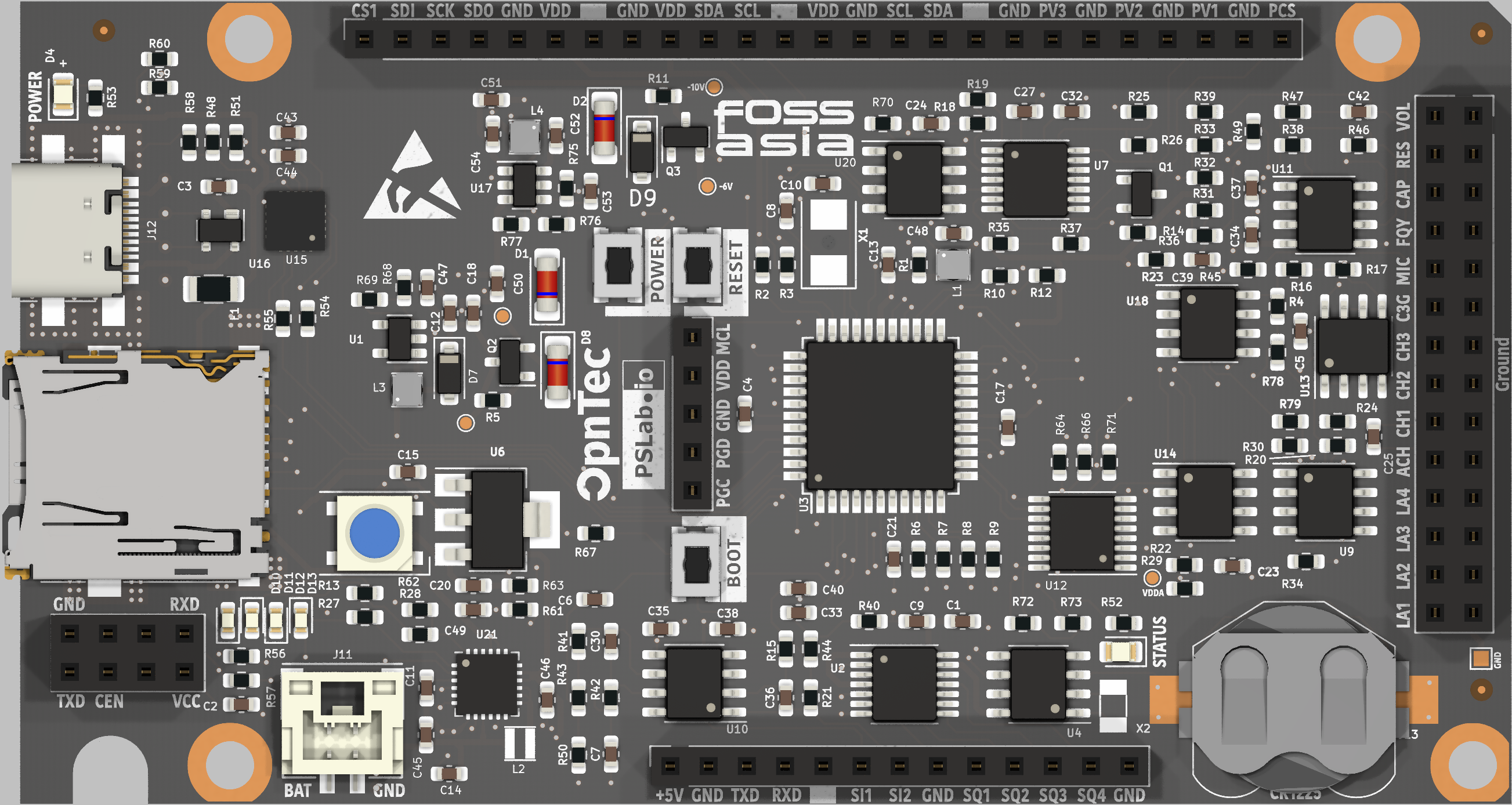 | 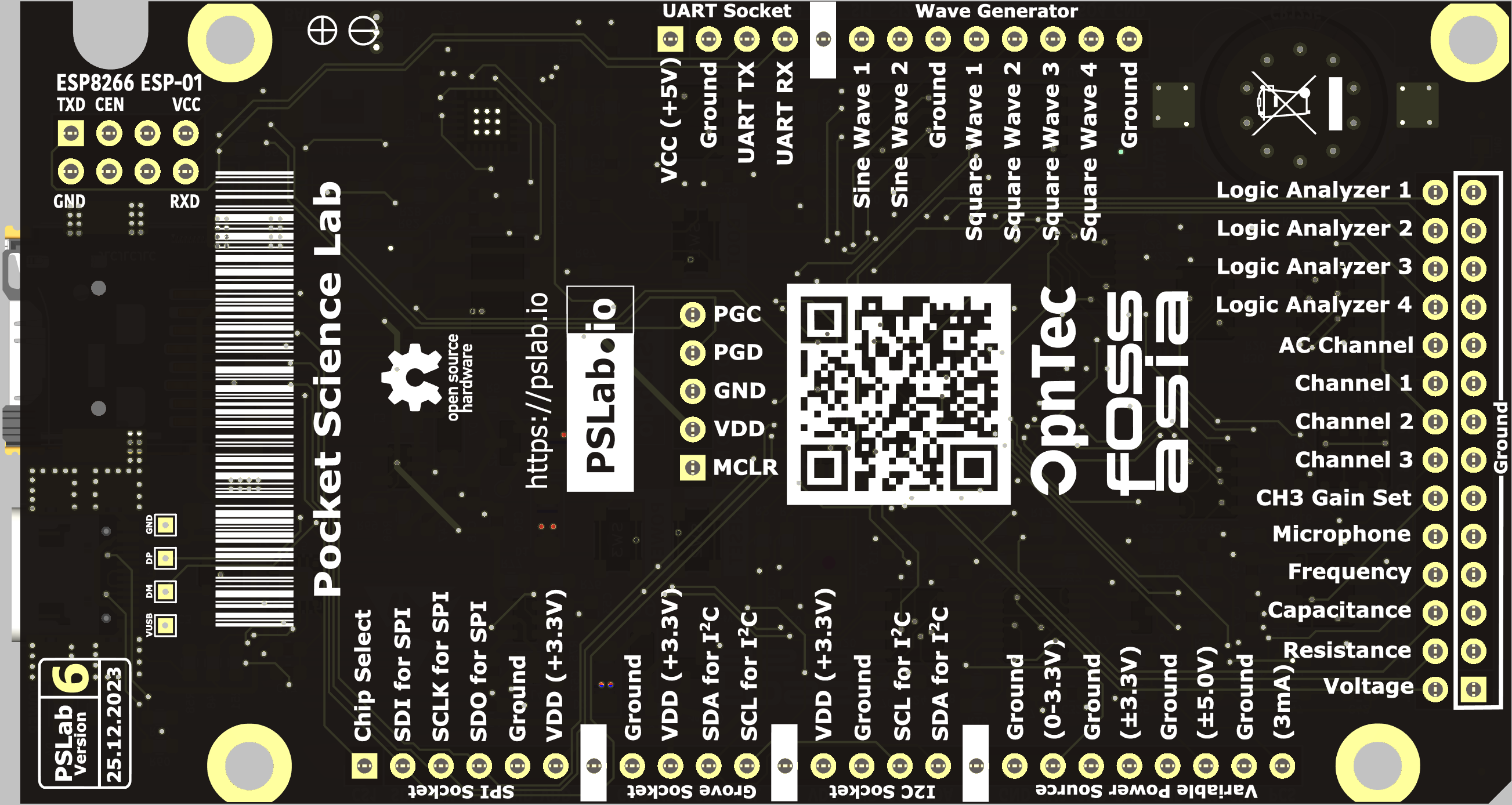 |
 |  |  |  |  |
|---|
The following software components are available:
📦pslab-hardware
 ┣ 📂archives                                   # Source files for previous PSLab versions
 ┃ ┣ 📂Breakout_Boards
 ┃ ┣ 📂PSLab KiCAD
 ┃ ┣ 📂PSLab KiCAD v2
 ┃ ┗ 📂PSLab KiCAD v3
 ┣ 📂docs                                       # Supplementary material
 ┃ ┣ 📂components
 ┃ ┃ ┣ 📜BillOfMaterials.csv                    # Component list
 ┃ ┃ ┗ 📜InteractiveBoM.html                    # Interactive version of BoM
 ┃ ┣ 📂datasheets                               # PDF datasheets for components used in PSLab
 ┃ ┣ 📂drawings                                 # CAD dimension drawings
 ┃ ┣ 📂images
 ┃ ┃ ┣ 📂pslab_version_previews
 ┃ ┃ ┣ 📜 ...
 ┃ ┃ ┗ 📜PSLab_v6_top.png
 ┃ ┣ 📂pin_layouts                              # Pin labels and specifications
 ┃ ┃ ┣ 📜PSLab_Pin_Layout.pdf
 ┃ ┃ ┗ 📜PSLab_Pin_Layout.svg
 ┃ ┣ 📂position_files
 ┃ ┃ ┗ 📜PositionFile.csv                       # Pick and place information
 ┃ ┣ 📂reference                                # TeX documentation (stale)
 ┃ ┗ 📂schematics
┃ ┃ ┗ 📜PSLab.pdf # Board schematic in PDF| Version | Content | Preview |
|---|---|---|
| PSLab KiCAD v1 | Original version with SEELABLET schematics and layout files |  |
| PSLab KiCAD v2 | Developed version with new additions (Voltage regulator, Oscillator) |  |
| PSLab KiCAD v3 | Device layout changed to Arduino Uno form factor | 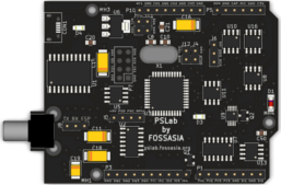 |
| PSLab KiCAD v4 | Assembly optimized version with Arduino Mega form factor having components mounted only on top side | 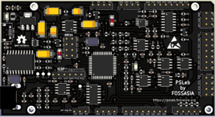 |
| PSLab KiCAD v5 | Added socket for external bluetooth module and bottom silk screen with pin description | 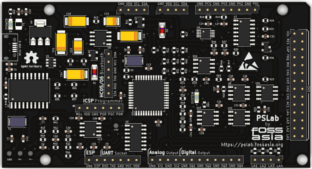 |
| PSLab KiCAD v6 | Added external power input, RTC module, SD Card slot, USB type C, ESP 01 and upgraded UART and power ICs | 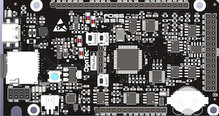 |
PIC24EP256GP204 - Microcontroller
MCP6S21 - Programmable gain amplifier
MCP4728 - 4 Channel DAC
TC7660 - Charge Pump voltage invertor
TC1240A - Charge Pump voltage doubler
TL082 - 2 channel Op-Amp
LM324 - 4 channel Op-Amp
DS1307Z+ - RTC module
LDFM33PUR - 3.3 V regulator
LDL212PU50R - 5.0 V regulator
CP2102N-A02-GQFN24 - USB-UART bridge
74HC126 - 4 channel buffer
SP0503BAHTG - ESD protector
0.5 A Fuse
Assorted resistors, capacitors & diodes
Find the complete bill of materials from this link.
Extension slots for an ESP is available.
One of the main features of PSLab is the 3-channel Oscilloscope which can monitor analog inputs at maximum of 2 million samples per second. It includes controls such as triggering, and gain selection. Uses Python-Scipy for curve fitting.
| Qty | Value | Footprint | References |
|---|---|---|---|
| 31 | 10k | Resistor_SMD:R_0603_1608Metric | R1, R10, R14, R16, R17, R18, R19, R21, R23, R25, R29, R31, R32, R33, R35, R37 +15 |
| 18 | 100nF | Capacitor_SMD:C_0603_1608Metric | C1, C2, C3, C4, C13, C17, C18, C24, C25, C27, C32, C34, C35, C37, C38, C39 +2 |
| 13 | 5.1k | Resistor_SMD:R_0603_1608Metric | R2, R3, R12, R15, R26, R41, R43, R44, R48, R52, R53, R59, R60 |
| 9 | 200 | Resistor_SMD:R_0603_1608Metric | R6, R7, R8, R9, R13, R27, R28, R49, R62 |
| 8 | 22uF | Capacitor_SMD:C_0603_1608Metric | C45, C46, C47, C48, C49, C50, C51, C54 |
| 7 | 10uF | Capacitor_SMD:C_0603_1608Metric | C6, C12, C14, C15, C21, C33, C44 |
| 7 | 200k | Resistor_SMD:R_0603_1608Metric | R20, R30, R40, R46, R50, R63, R77 |
| 5 | 1k | Resistor_SMD:R_0603_1608Metric | R5, R11, R36, R47, R51 |
| 5 | TEST | PSLab:Test_Point_0.8mm | TP1, TP2, TP3, TP5, TP6 |
| 4 | 10nF | Capacitor_SMD:C_0603_1608Metric | C5, C7, C23, C40 |
| 4 | 18 | Resistor_SMD:R_0603_1608Metric | R54, R55, R56, R57 |
| 4 | TL082 | Package_SO:SOIC-8_3.9x4.9mm_P1.27mm | U9, U10, U11, U13 |
| 4 | White | LED_SMD:LED_0603_1608Metric | D10, D11, D12, D13 |
| 3 | 12pF | Capacitor_SMD:C_0603_1608Metric | C8, C10, C53 |
| 3 | 1M | Resistor_SMD:R_0603_1608Metric | R24, R34, R45 |
| 3 | 1uF | Capacitor_SMD:C_0603_1608Metric | C20, C42, C52 |
| 3 | 3.3uH | Inductor_SMD:L_Taiyo-Yuden_MD-2020 | L1, L3, L4 |
| 3 | Fiducial | Fiducial:Fiducial_0.5mm_Mask1.5mm | FID1, FID2, FID3 |
| 3 | M | PSLab:OneSided_MPad | MH1, MH2, MH3 |
| 3 | SW_MEC_5E | PSLab:button_SPST_3x4x2.5 | SW1, SW2, SW3 |
| 2 | 1nF | Capacitor_SMD:C_0603_1608Metric | C30, C36 |
| 2 | 6.8V | Diode_SMD:D_MiniMELF | D1, D2 |
| 2 | GND | TestPoint:TestPoint_Pad_1.0x1.0mm | TP4, TP7 |
| 2 | MCP6S21 | Package_SO:SOIC-8_3.9x4.9mm_P1.27mm | U14, U18 |
| 2 | MMBT3906 | Package_TO_SOT_SMD:SOT-23 | Q1, Q3 |
| 2 | OpenHardware | Symbol:OSHW-Logo_5.7x6mm_SilkScreen | Z11, Z11 |
| 1 | 100k | Resistor_SMD:R_0603_1608Metric | R75 |
| 1 | 12MHz | Crystal:Crystal_SMD_5032-2Pin_5.0x3.2mm | X1 |
| 1 | 12k | Resistor_SMD:R_0603_1608Metric | R22 |
| 1 | 180k | Resistor_SMD:R_0603_1608Metric | R68 |
| 1 | 1A | Fuse:Fuse_1206_3216Metric | F1 |
| 1 | 1N4148W | Diode_SMD:D_SOD-123 | D9 |
| 1 | 1N4148W | Diode_SMD:D_MiniMELF | D8 |
| 1 | 2.2uF | Capacitor_SMD:C_0603_1608Metric | C11 |
| 1 | 30k | Resistor_SMD:R_0603_1608Metric | R69 |
| 1 | 32.768 kHz | Crystal:Crystal_SMD_3215-2Pin_3.2x1.5mm | X2 |
| 1 | 4.7uH | Inductor_SMD:L_Taiyo-Yuden_MD-2020 | L2 |
| 1 | 51k | Resistor_SMD:R_0603_1608Metric | R61 |
| 1 | 74HC126 | Package_SO:TSSOP-14_4.4x5mm_P0.65mm | U2 |
| 1 | 74HC4051 | Package_SO:TSSOP-16_4.4x5mm_P0.65mm | U12 |
| 1 | AMS1117-3.3 | Package_TO_SOT_SMD:SOT-223-3_TabPin2 | U6 |
| 1 | AP3015A | Package_TO_SOT_SMD:SOT-23-5 | U1 |
| 1 | BLUE | LED_SMD:LED_0805_2012Metric | D4 |
| 1 | Battery_Cell | PSLab:2.0mm_connector_edge | J11 |
| 1 | CP2102N-xxx-xQFN20x | PSLab:QFN-20_EP_3x3_Pitch0.5mm | U15 |
| 1 | CR1225 | Battery:Battery_CR1225 | Z1 |
| 1 | CR1225 | PSLab:BatteryHolder_A359 | J13 |
| 1 | Conn_01x13 | Connector_PinSocket_2.54mm:PinSocket_1x13_P2.54mm_Vertical | J3 |
| 1 | Conn_01x25 | Connector_PinSocket_2.54mm:PinSocket_1x25_P2.54mm_Vertical | J2 |
| 1 | D+ | TestPoint:TestPoint_Pad_1.0x1.0mm | TP10 |
| 1 | D- | TestPoint:TestPoint_Pad_1.0x1.0mm | TP9 |
| 1 | DS1307Z+T&R | Package_SO:SOIC-8_3.9x4.9mm_P1.27mm | U4 |
| 1 | DoublePins | Connector_PinSocket_2.54mm:PinSocket_2x14_P2.54mm_Vertical | J1 |
| 1 | ESD-Logo | Symbol:ESD-Logo_6.6x6mm_SilkScreen | Z10 |
| 1 | ESP01 | PSLab:ESP-01 | J6 |
| 1 | GREEN | LED_SMD:LED_0805_2012Metric | D3 |
| 1 | IP5189T | Package_DFN_QFN:QFN-24-1EP_4x4mm_P0.5mm_EP2.6x2.6mm | U21 |
| 1 | K1N5817HW-7-F | Diode_SMD:D_SOD-123 | D7 |
| 1 | LM324 | Package_SO:TSSOP-14_4.4x5mm_P0.65mm | U7 |
| 1 | M | PSLab:TwoSided_MPad | MH4 |
| 1 | MCP4822 | Package_SO:SOIC-8_3.9x4.9mm_P1.27mm | U20 |
| 1 | MMBT3904 | Package_TO_SOT_SMD:SOT-23 | Q2 |
| 1 | MT1470 | Package_TO_SOT_SMD:SOT-23-6 | U17 |
| 1 | Micro_SD_Card_Det_9_pin | PSLab:TF-015 | J8 |
| 1 | PIC24EP256GP204 | Package_QFP:TQFP-44_10x10mm_P0.8mm | U3 |
| 1 | PSLab BarCode | PSLab:Barcode | Z7 |
| 1 | Programmer | Connector_PinSocket_2.54mm:PinSocket_1x05_P2.54mm_Vertical | J10 |
| 1 | SP0503BAHT | Package_TO_SOT_SMD:SOT-143 | U16 |
| 1 | Silk | PSLab:PSLab_SilkScreen | Z9 |
| 1 | USB_C_Receptacle | PSLab:USB_C_Receptacle_12pin_SMT | J12 |
| 1 | VBUS | TestPoint:TestPoint_Pad_1.0x1.0mm | TP8 |
| 1 | WS2812B | PSLab:LED_WS2812B_PLCC4_5.0x5.0mm_P3.2mm | D5 |
| 1 | eWaste | Symbol:WEEE-Logo_4.2x6mm_SilkScreen | Z6 |
fossasia/pslab-hardware
PSLab Hardware Design and Schematics https://pslab.io


dilshan/programmable-light
Simple time based programmable light controller


It measures 99 × 53.3 mm and has 4 copper layers, 1.6 mm thick.
199 parts, built around the PIC24EP256GP204-I/PT, 74HC126D, TL082 and MCP6S21-I/P. The full list of its parts is on this page, with links to each part's symbol and footprint where PCBKit's library has them.
From the fossasia/pslab-hardware repository on GitHub, at the commit this page was made from: the board is schematics/PSLab.kicad_pcb and its schematic schematics/PSLab.kicad_sch. PCBKit opens the board in the browser, with nothing to install.
Its repository publishes it under the Apache-2.0 licence: you may reuse it on that licence's terms (keep the author's notice, and for a copyleft licence share your changes alike).