2 layers40 × 40 mm
Airqualitymini
MorgenWebDigital/airqualitymini
A stationary indoor air quality sensor. Real CO₂, VOC and NOx, temperature and humidity. No display, no battery. Powered from USB-C, read out over Bluetooth LE.
32 parts

 MorgenWebDigital/airquality
A battery-powered indoor air quality monitor. Real CO₂ from a photoacoustic sensor, VOC and NOx, temperature, humidity and ambient light, shown on a 2.13" e-paper display and sent over Bluetooth LE.
Airquality is an open-source printed circuit board by MorgenWebDigital, from the MorgenWebDigital/airquality repository on GitHub. It is a 2-layer board of 45 × 95 mm with 78 parts on 94 nets, routed with 739 tracks and 117 vias.
It is built around the ESP32-C3-WROOM-02-N4, BH1750FVI-TR and CH224K, with the SCD40-D-R1, SGP41-D-R4 and SHT41-AD1B-R2 among its other parts. Its parts include 36 capacitors, 15 ICs, 14 resistors, 3 diodes and 2 transistors. It belongs with the sensors and measurement boards and the ESP32 and RISC-V boards of this library.


A battery-powered indoor air quality monitor. Real CO₂ from a photoacoustic sensor, VOC and NOx, temperature, humidity and ambient light, shown on a 2.13" e-paper display and sent over Bluetooth LE.
Two layers, 45 × 95 mm, 76 electrical components, one 21700 lithium cell.
| front | back |
|---|---|
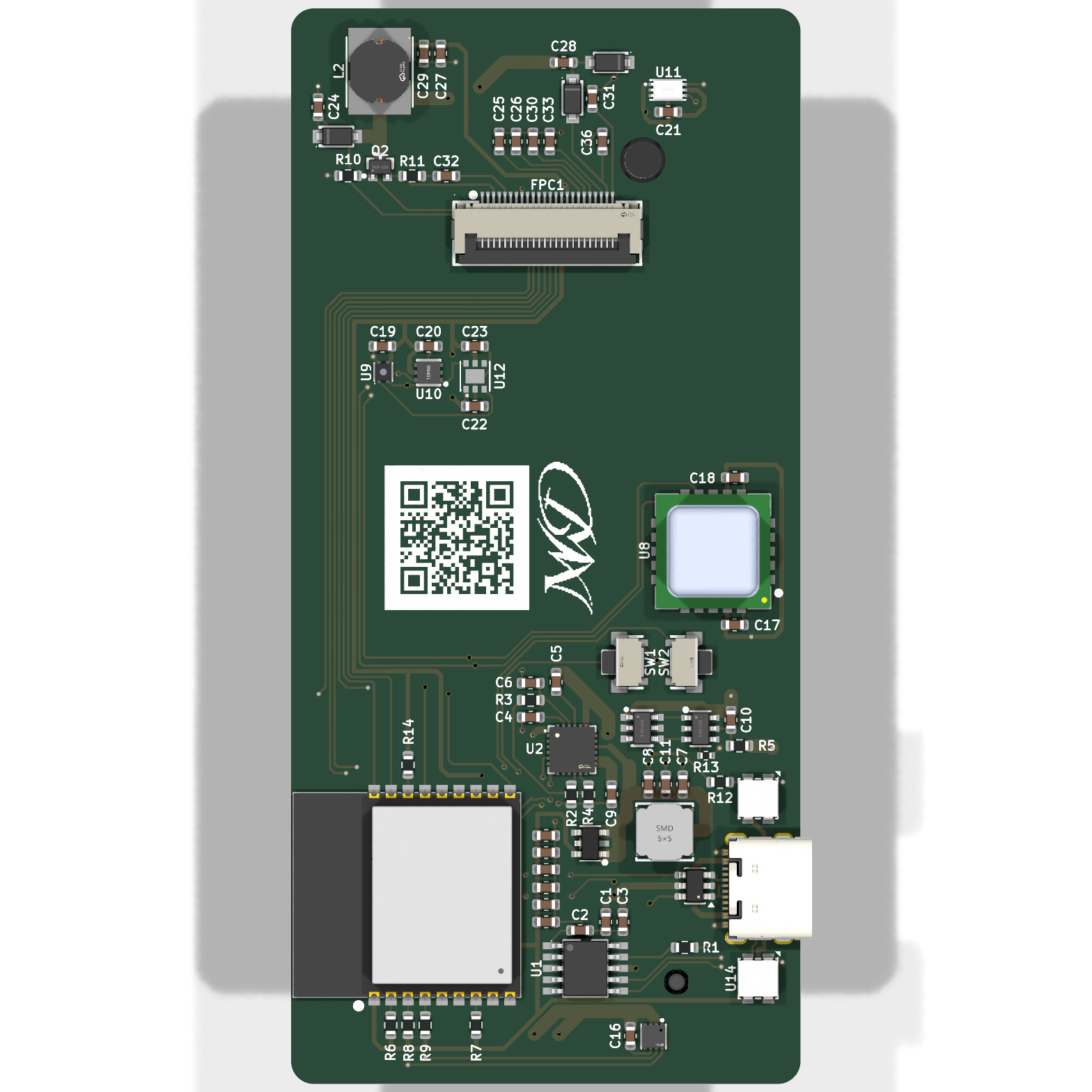 | 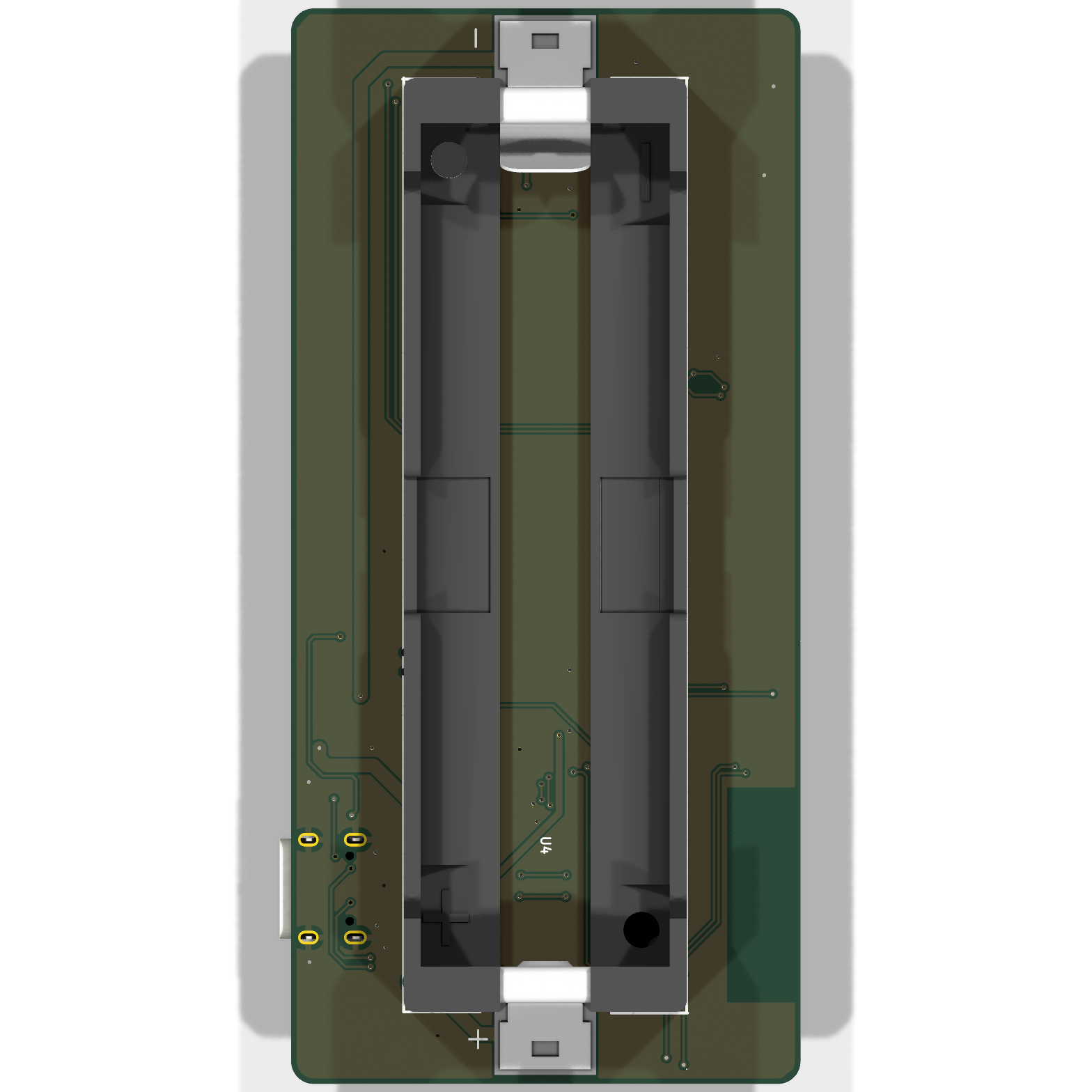 |
| Sensor | Measures | Accuracy | I²C |
|---|---|---|---|
| SCD40 | CO₂, photoacoustic, a real measurement rather than an estimate | ±(50 ppm + 5 % of reading) | 0x62 |
| SGP41 | VOC and NOx index | index, not a concentration | 0x59 |
| SHT41 | humidity and temperature | ±1.8 %RH, ±0.2 °C | 0x44 |
| T117Z | temperature, the precision channel | ±0.1 °C, 16 bit | 0x48 |
| BH1750 | ambient light | 1 lx resolution, 1–65535 lx | 0x23 |
| MAX17048 | state of charge of the cell | ±1 %, no shunt needed | 0x36 |
| BQ25895 | charger status and control | - | 0x6A |
Everything shares one I²C bus. The addresses do not collide.
The SCD40 is the only sensor that measures CO₂ directly. The SGP41 reports a VOC and a NOx index derived from a heated metal-oxide cell. That reads as "the air is getting stale", and is not comparable to a ppm figure.
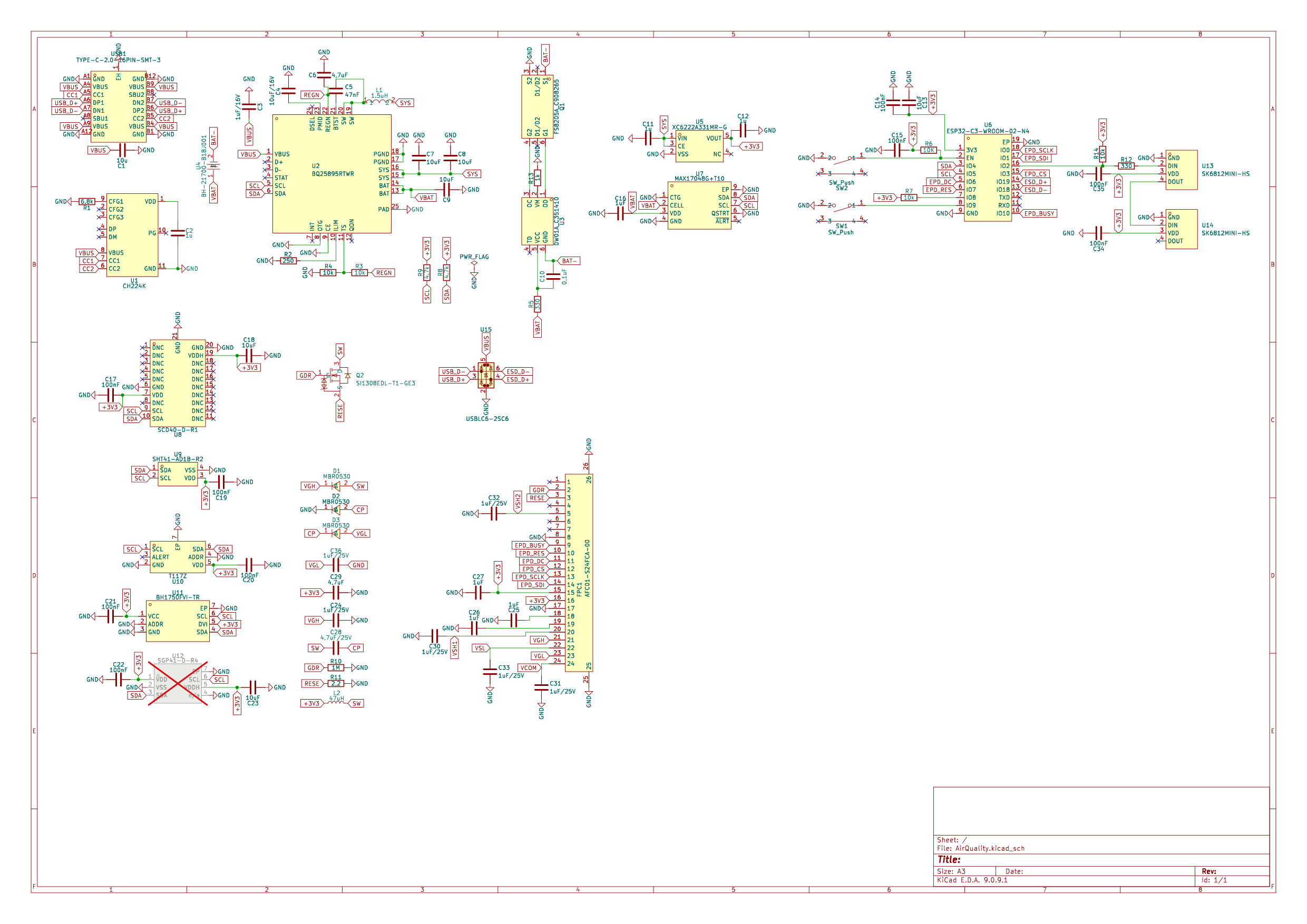
The full schematic as a PDF is in docs/schematic.pdf.
   USB-C ──▶ CH224K ──▶ VBUS ──▶ BQ25895 ──▶ SYS ──▶ XC6222 ──▶ 3.3 V
             requests            charger            LDO         MCU, sensors,
             9 V over PD                                        display
                                    │
                                    ▼
                                  21700 cell
                                    │
                              DW01A + FS8205A
                              cell protection
The CH224K negotiates 9 V over USB Power Delivery. At 9 V the charger draws about half the current it would at 5 V for the same charging power. Less loss in the cable, less heat. A 6.8 kΩ resistor on CFG1 selects the voltage; the value comes straight from the table in the CH224K datasheet.
The BQ25895 is a switching charger, not a linear one. It can deliver up to 5 A; the input current limit is set by a 250 Ω resistor to about 2.1 A. It also provides the power path, so the device runs from USB while charging.
The cell is a Molicel INR21700-P45B, which ships unprotected. DW01A with an FS8205A dual MOSFET adds over-charge, over-discharge and over-current protection. A 1 kΩ resistor sits between the DW01A's VM pin and the pack negative, as the datasheet's application circuit requires. Without it, plugging in a charger while the protection has tripped puts the full charger voltage on that pin with nothing to limit the current.
The XC6222 drops SYS to 3.3 V. Its CE pin is tied to SYS: the regulator is always on while the cell has charge. It cannot be switched off from the ESP32, because the ESP32 hangs on that same rail and could never switch it back on.
A 2.13" e-paper panel (GDEY0213B74, SSD1680 controller) on a 24-pin 0.5 mm FPC connector. Bistable: it holds the image with no power at all, and only draws current while updating.
The panel needs gate and source rails well beyond 3.3 V. They are generated on the board, following the reference circuit in the panel's datasheet:
All seven capacitors on these rails are rated 25 V. That is not decoration: VGH runs above 20 V, and a standard 1 µF 0603 from the shelf is often a 6.3 or 16 V part.
BS1 is tied low, which selects 4-wire SPI, matching the SDA/SCL/CS/DC/RES wiring used here.
Update budget. The panel is rated for one million updates or five years, whichever comes first. At one update per minute the update budget is gone in under two years; at three minutes and longer, the five-year limit is reached first. Redrawing no more often than every three minutes, and only when a value actually changes, keeps the panel inside both limits.
| Size | 45 × 95 mm |
| Layers | 2, 35 µm copper |
| Ground | pour on the back, 3306 mm² |
| Minimum clearance | 0.2 mm |
| Minimum track | 0.2 mm |
| Vias | 0.6 mm pad, 0.3 mm drill |
The ESP32 antenna sits at the board edge with a keep-out on both copper layers. Nothing is routed through it: no track, no via, no pour.
ESD protection on the USB data lines: a USBLC6-2SC6 sits 1.9 mm from the connector pads, with the signal routed through the device rather than branched off it, and a ground via right at its ground pad. Both matter more than they look: an ESD pulse rises in under a nanosecond, and every millimetre of track between the connector and the clamp adds roughly 35 V of overshoot that the ESP32 then sees.
U12 (SGP41) is marked do-not-populate. The footprint and routing are there; the part is left off in the current build. Fitting it later needs no board change.
Everything needed is in this repository.
Boards. production/AirQuality-gerber.zip goes straight to a
fab house. Two layers, 1.6 mm, 35 µm copper, any standard process. The zip holds
the Gerbers and the Excellon drill files.
Parts. production/AirQuality-bom.csv lists every component
with its LCSC number where one exists.
production/AirQuality-positions.csv is the pick-and-place file.
Datasheets for every active part are in datasheets/, named
by LCSC part number.
Opening the design. KiCad 9. Open
hardware/AirQuality.kicad_pro. All symbols, footprints and 3D
models live in hardware/libraries/ and are referenced relatively, so the
project opens from any location.
Mechanical. docs/AirQuality.step is the full board with all
components, for enclosure design.
Longer notes on why things are the way they are:
docs/design-notes.md: component choices and the
reasoning behind themdocs/track-widths.md: current, trace widths and
the IPC-2221 arithmeticThe board passes with no electrical findings:
   ERC                      0 errors, 0 warnings
   Unconnected pads         0
   Shorts                   0
   Clearance violations     0
   Schematic parity         0
Every integrated circuit has been checked pin by pin against its datasheet. Not
against memory or a symbol's label, but against the document in
datasheets/.
Remaining DRC output is silkscreen only: reference designators over copper and part outlines crossing the board edge at the connectors. Neither affects manufacture.
PolyForm Noncommercial 1.0.0. Any use is permitted except a commercial one.
| Qty | Value | Footprint | References |
|---|---|---|---|
| 9 | 100nF | Capacitor_SMD:C_0603_1608Metric | C14, C15, C17, C19, C20, C21, C22, C34, C35 |
| 6 | 10uF | Capacitor_SMD:C_0603_1608Metric | C7, C8, C9, C13, C18, C23 |
| 6 | 1uF/25V | Capacitor_SMD:C_0603_1608Metric | C24, C30, C31, C32, C33, C36 |
| 4 | 10k | Resistor_SMD:R_0603_1608Metric | R3, R4, R7, R14 |
| 4 | 1uF | Capacitor_SMD:C_0603_1608Metric | C16, C25, C26, C27 |
| 3 | 1u | Capacitor_SMD:C_0603_1608Metric | C2, C11, C12 |
| 3 | MBR0530 | AirQuality:SOD-123_L2.8-W1.8-LS3.7-RD | D1, D2, D3 |
| 2 | 330 | Resistor_SMD:R_0603_1608Metric | R5, R12 |
| 2 | 4,7uF | Capacitor_SMD:C_0603_1608Metric | C6, C29 |
| 2 | 4.7k | Resistor_SMD:R_0603_1608Metric | R8, R9 |
| 2 | SK6812MINI-HS | AirQuality:LED-SMD_4P-L3.5-W3.5-BR_SK6812MINI-HS | U13, U14 |
| 2 | SW_Push | AirQuality:SW-SMD_2P-TS24CA | SW1, SW2 |
| 1 | 0,1uF | Capacitor_SMD:C_0603_1608Metric | C10 |
| 1 | 1.5uH | AirQuality:IND-SMD_L5.0-W5.0_SWPA5040S | L1 |
| 1 | 10K | Resistor_SMD:R_0603_1608Metric | R6 |
| 1 | 10u | Capacitor_SMD:C_0603_1608Metric | C1 |
| 1 | 10uF/16V | Capacitor_SMD:C_0603_1608Metric | C4 |
| 1 | 1M | Resistor_SMD:R_0603_1608Metric | R10 |
| 1 | 1k | Resistor_SMD:R_0402_1005Metric | R13 |
| 1 | 1uF/16V | Capacitor_SMD:C_0603_1608Metric | C3 |
| 1 | 2,2 | Resistor_SMD:R_0603_1608Metric | R11 |
| 1 | 250 | Resistor_SMD:R_0603_1608Metric | R2 |
| 1 | 4,7uF/25V | Capacitor_SMD:C_0603_1608Metric | C28 |
| 1 | 47nF | Capacitor_SMD:C_0603_1608Metric | C5 |
| 1 | 47uH | AirQuality:IND-SMD_L5.8-W5.2 | L2 |
| 1 | 6.8k | Resistor_SMD:R_0603_1608Metric | R1 |
| 1 | AFC01-S24FCA-00 | AirQuality:FPC-SMD_24P-P0.50_AFC01-S24FCA-00 | FPC1 |
| 1 | BH-21700-B1BJ001 | AirQuality:BAT-SMD_L82.5.5-W25-BH-21700-B1BJ001 | U4 |
| 1 | BH1750FVI-TR | AirQuality:WSOF-6_L2.6-W1.6-P0.50-TL-EP | U11 |
| 1 | BQ25895RTWR | AirQuality:QFN-24_L4.0-W4.0-P0.50-TL-EP2.7 | U2 |
| 1 | CH224K | AirQuality:ESSOP-10_L4.9-W3.9-P1.0-LS6.0-TL-EP | U1 |
| 1 | DW01A_C351410 | AirQuality:SOT-23-6_L2.9-W1.6-P0.95-LS2.8-BL | U3 |
| 1 | ESP32-C3-WROOM-02-N4 | AirQuality:BULETM-SMD_ESPRESSIF_ESP32-C3-WROOM-02-N4-4MB | U6 |
| 1 | FS8205A_C908265 | AirQuality:SOT-23-6_L2.9-W1.6-P0.95-LS2.8-BR | Q1 |
| 1 | MAX17048G+T10 | AirQuality:TDFN-8_L2.0-W2.0-P0.50-BL-EP1.2 | U7 |
| 1 | MWD_Logo | AirQuality:MWD_Logo | LOGO |
| 1 | SCD40-D-R1 | AirQuality:LGA-20_L10.1-W10.1-P1.25-TL | U8 |
| 1 | SGP41-D-R4 | AirQuality:DFN-6_L2.4-W2.4-P0.80-TL-EP | U12 |
| 1 | SHT41-AD1B-R2 | AirQuality:DFN-4_L1.5-W1.5-SHT41-AD1B-R2 | U9 |
| 1 | SI1308EDL-T1-GE3 | AirQuality:SOT-323_L2.0-W1.3-P1.30-LS2.1-BR | Q2 |
| 1 | T117Z | AirQuality:TDFN-6_L2.0-W2.0-P0.65-TL-EP | U10 |
| 1 | TYPE-C-2.0-16PIN-SMT-3 | AirQuality:TYPE-C-SMD_TYPE-CF3.1 | USB1 |
| 1 | USBLC6-2SC6 | Package_TO_SOT_SMD:SOT-23-6 | U15 |
| 1 | XC6222A331MR-G | AirQuality:SOT-25-5_L2.9-W1.6-P0.95-LS2.8-BR | U5 |
| 1 | https://github.com/MorgenWebDigital | MWD_QR_GitHub | QR |
It measures 45 × 95 mm and has 2 copper layers, 1.6 mm thick.
78 parts, built around the ESP32-C3-WROOM-02-N4, BH1750FVI-TR, CH224K and SCD40-D-R1. The full list of its parts is on this page, with links to each part's symbol and footprint where PCBKit's library has them.
From the MorgenWebDigital/airquality repository on GitHub, at the commit this page was made from: the board is hardware/AirQuality.kicad_pcb and its schematic hardware/AirQuality.kicad_sch. PCBKit opens the board in the browser, with nothing to install.
Its repository states no licence, so its author keeps all rights: ask MorgenWebDigital before reusing the design.
MorgenWebDigital/airqualitymini
A stationary indoor air quality sensor. Real CO₂, VOC and NOx, temperature and humidity. No display, no battery. Powered from USB-C, read out over Bluetooth LE.


JonaWe/ummon
ummon (from German Umgebungsmonitor, "environment monitor") is an ESP32-C6 based environmental sensor board with USB-C power.


LimesKey/parsnip-node
A portable LoRa communicator. Custom 4-layer PCB (ESP32-S3 + E22P-915M30S LoRa + NEO-M9N GNSS), designed in KiCad for 915 MHz.
